Machine tool cutter temperature control device

A temperature control device and cutting tool technology, which is applied in the direction of manufacturing tools, metal processing machinery parts, maintenance and safety accessories, etc., can solve the problems of cutting fluid cooling, polluting the environment, and difficult recycling, so as to achieve the goal of clean production and ensure cutting quality , power controllable effect

Inactive Publication Date: 2021-03-26
NANCHANG HANGKONG UNIVERSITY
View PDF12 Cites 2 Cited by
  • Summary
  • Abstract
  • Description
  • Claims
  • Application Information

AI Technical Summary

Problems solved by technology

[0003] The purpose of the present invention is to provide a machine tool tool temperature control device, which overcomes the shortcomings of the original tool that uses cutting fluid to cool the environment and seriously pollutes the environment and is not easy to recycle.

Method used


Image

  • Machine tool cutter temperature control device
  • Machine tool cutter temperature control device
  • Machine tool cutter temperature control device

Examples


Embodiment approach

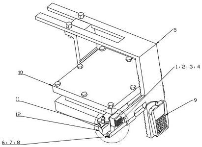
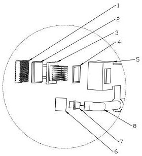
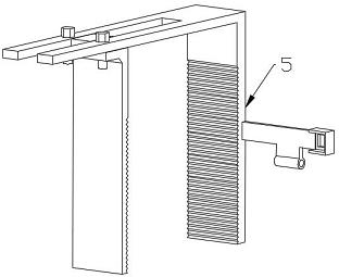
[0014] A machine tool tool temperature control device, characterized in that it includes a cooling block 1, a cooling semiconductor 2, a radiator 3, a rubber gasket 4, a movable fixture 5, a temperature sensor 7, an adjustable sleeve 8, a controller assembly 9, and a guide The cold block 1 is close to the handle 12, and the heat-conducting silicone grease is used as the contact medium in the middle. The cooling side of the cooling semiconductor 2 is close to the cold guide block 1, the heat dissipation side is close to the radiator 3, and the fin side of the radiator 3 is covered with a rubber gasket 4. During installation, first put the rubber gasket 4 into the fixed frame at the front end of the movable fixture 5; in the second step, install the radiator 3, and one side of the fins of the radiator 3 passes through the rubber gasket 4 and the frame opening of the fixed frame in turn; the third step, Install the cooling semiconductor 2, apply heat-conducting silicone grease on...


PUM


Abstract

The invention discloses a machine tool cutter temperature control device capable of replacing cutting fluid. The machine tool cutter temperature control device is characterized by comprising a cold conduction block, a cooling semiconductor, a radiator, a rubber gasket, a movable clamp, a temperature sensor, an adjustable sleeve and a controller assembly, wherein the cold conduction block is in contact with a cutter handle through heat conduction silicone grease; cutter waste heat is absorbed through the Peltier effect of the cooling semiconductor; and the waste heat is transmitted to the radiator through a heat conduction plate so as to be dissipated. A temperature monitoring module monitors the contact temperature of a cutter and a workpiece in real time through an infrared radiation sensor and inputs a signal to the controller assembly, and the controller assembly adjusts the current passing through the cooling semiconductor according to the preset temperature and the real-time temperature so as to control refrigeration power. According to the machine tool cutter temperature control device provided by the invention, no cutting fluid is needed, no waste liquid is discharged, no noise is generated, continuous work can be achieved, the power is controllable, high-precision temperature control can be achieved, and the cutter and a cutting material can be reversely heated under the special process requirement.

Description

technical field [0001] The invention relates to a temperature control device for a machine tool which replaces cutting fluid. Background technique [0002] In machining and manufacturing, when metal is cut, the work done by the shear deformation of the chip and the work done by the front and rear friction of the tool are all converted into heat, which is called cutting heat. Cutting heat affects tool life and cutting quality. Cutting fluid is widely used to cool workpieces, resulting in a large amount of waste cutting fluid. Traditional cutting waste cooling cutting fluid pollutes the environment and is not conducive to clean production. Cutting fluid wastewater contains a large amount of emulsified oil, additives such as surfactants, corrosion inhibitors, and defoamers, as well as impurities such as waste oil, dust, and metal shavings, and must be strictly treated before being discharged. The cutting waste liquid is directly discharged into the natural water body, which ...

Claims


Application Information

Patent Timeline
Patent Type & Authority Applications(China)
IPC IPC(8): B23Q11/00
CPCB23Q11/00
Inventor 黄帅秦国华
Owner NANCHANG HANGKONG UNIVERSITY
Why Eureka
Try Eureka