Sight tracking method of intelligent glasses based on MEMS and optical waveguide lenses

An eye-tracking and optical waveguide technology, applied in the field of eye-tracking, can solve the problems of reducing the user experience of VR/AR applications, poor sensitivity, high power consumption, etc.

Active Publication Date: 2021-03-26
幻蝎科技(武汉)有限公司
View PDF13 Cites 11 Cited by
  • Summary
  • Abstract
  • Description
  • Claims
  • Application Information

AI Technical Summary

Problems solved by technology

[0016] (1) Traditional eye trackers are slow, cumbersome, intrusive and restrictive for users
[0017] (2) Traditional systems usually require cameras and imaging processing software, which are often expensive, slow to calculate and consume power, and the eyeball sampling rate depends on the frame rate of the camera
[0018] (3) The camera and the infrared light source transmitter are set around the optical imaging element (optical waveguide) of the smart glasses, and need to be set at a position where the camera can shoot the eyeball and the light source can illuminate the eyeball. When the field of view of the smart glasses is sufficient When it is large, the camera and infrared light source will limit the range of field of view, which is not conducive to the lightweight design of smart glasses, resulting in a decline in the overall immersion and experience of smart glasses
[0019] (4) Traditional systems exhibit a significant lag between the actual eye movement and the computationally measured eye position, i.e. low sampling rate, degrading user experience in VR/AR applications
[0020] (5) The electric eye diagram will be affected...

Method used


Image

  • Sight tracking method of intelligent glasses based on MEMS and optical waveguide lenses
  • Sight tracking method of intelligent glasses based on MEMS and optical waveguide lenses
  • Sight tracking method of intelligent glasses based on MEMS and optical waveguide lenses

Examples


Embodiment Construction

[0152] In order to make the object, technical solution and advantages of the present invention more clear, the present invention will be further described in detail below in conjunction with the examples. It should be understood that the specific embodiments described here are only used to explain the present invention, not to limit the present invention.

[0153] Aiming at the problems existing in the prior art, the present invention provides a line-of-sight tracking method based on an optical waveguide lens for a near-eye display device. The present invention will be described in detail below with reference to the accompanying drawings.

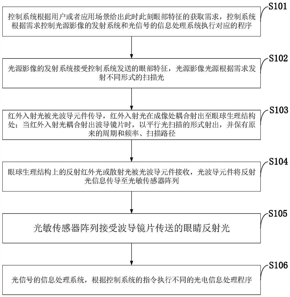
[0154] Such as figure 1 As shown, the eye-tracking method based on the optical waveguide lens for the near-eye display device provided by the embodiment of the present invention includes the following steps:

[0155] S101: The control system gives the acquisition requirements of eye features at this moment according to the user or the app...


PUM


Abstract

The invention belongs to the technical field of sight tracking, and discloses a sight tracking method of intelligent glasses based on MEMS and optical waveguide lenses. Continuous and periodic scanning laser emitted by an MEMS scanning mirror is transmitted to the front of human vision through an optical waveguide element to be coupled out, a specific scanning path is formed on the surface of theeye, and some light enters the retina at a certain moment; reflected light on the retina is received and coupled by the optical coupling element in front of the vision, enters the optical waveguide element and is further transmitted to the photosensitive sensor; and the two-dimensional scanning laser path position information isconverted into one-dimensional time information according to the distribution intensity of the reflected light of the retina and the time period of the scanning light, and the position of the fixation point is calculated. The eye movement tracking method is low in powerconsumption, small in size and high in sampling rate, eye movement calibration is not needed, seamless switching of multiple functions of eyeball tracking, pupil recognition, iris recognition, diopter detection and eye health detection is achieved, and power consumption is reduced.

Description

technical field [0001] The invention belongs to the technical field of line of sight tracking, and in particular relates to a line of sight tracking method for smart glasses based on MEMS and optical waveguide lenses. In particular, it relates to a line-of-sight tracking method based on an optical waveguide lens and a MEMS scanning mirror for a near-eye display device. Background technique [0002] Currently, the closest prior art: Human eye movement can reveal a wealth of information about the neural mechanisms of the brain and vision, as well as an individual's neurological health, eye health, interests, and psychological state. Furthermore, eye tracking can be used to improve / enhance human-computer interaction, enable gaze-based human-machine interfaces, and enhance the way of interacting with wearable technologies. For example, gaze tracking, which relies on eye tracking, enables many augmented alternative communication (AAC) devices to enhance the abilities of individu...

Claims


Application Information

Patent Timeline
IPC IPC(8): G06F3/01G02B27/01
CPCG06F3/013G02B27/017G02B2027/0178
Inventor 陈涛
Owner 幻蝎科技(武汉)有限公司
Why Eureka
Try Eureka