Electromagnetically-driven organic solid waste pyrolysis system and method

An organic solid waste, electromagnetically driven technology, applied in combustion methods, lighting and heating equipment, combustion types, etc., can solve the problems of low energy utilization rate and high cost, and achieve the effect of improving heat energy utilization rate, low cost and reducing diffusion.

Inactive Publication Date: 2021-04-09
GUANGZHOU INST OF ENERGY CONVERSION - CHINESE ACAD OF SCI +1
View PDF6 Cites 2 Cited by
  • Summary
  • Abstract
  • Description
  • Claims
  • Application Information

AI Technical Summary

Problems solved by technology

[0004] The purpose of the present invention is to provide an electromagnetically driven organic solid waste pyrolysis system and method to solve the problems of low energy utilization and high cost of existing pyrolysis gasification technology

Method used


Image

  • Electromagnetically-driven organic solid waste pyrolysis system and method
  • Electromagnetically-driven organic solid waste pyrolysis system and method

Examples


Embodiment 1

[0043] 1) Clean the bean dregs, filter out most of the water, put them in a drying oven, and set the temperature at 60-150°C to dry overnight.

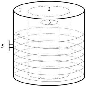
[0044] 2) Grind the dried okara into powder in a pulverizer, take an appropriate amount of okara powder and iron powder, mix them evenly, and put them into the inner tank 3 at a ratio of 1:1 to 1:10.

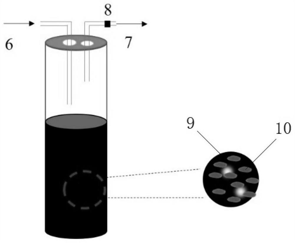
[0045] 3) Put the liner 3 into the cavity 2, cover the sealing cover and connect the intake pipe 6 and the exhaust pipe 7. Before the system starts to work, set the nitrogen gas on the controller 5 for 0 to 60 minutes to remove the internal gas. The air inside the gall 3.

[0046] 4) After the exhaust is finished, set the reaction time at 0-180min and the reaction temperature at 400-1000°C. After the parameter setting is completed, click Run on the controller 5, and the frequency conversion electromagnetic coil 4 will officially start running, and the inner tank 3 The iron powder in the absorbing electromagnetic coil 4 generates heat u...

example 2

[0051] 1) Clean the distiller's grain fine residue, filter out most of the water, put it into a drying oven, and set the temperature at 60-150°C to dry overnight.

[0052] 2) Grind the dried distiller's grains fine residue into powder in a pulverizer, take an appropriate amount of distiller's grain fine residue powder and iron powder, mix them evenly, and put them into the inner tank 3 at a ratio of 1:1 to 1:10.

[0053] 3) Put the liner 3 into the cavity 2, cover the sealing cover and connect the intake pipe 6 and the exhaust pipe 7. Before the system starts to work, set the nitrogen gas on the controller 5 for 0 to 60 minutes to remove the internal gas. The air inside the gall 3.

[0054] 4) After the exhaust is finished, set the reaction time at 0-180min and the reaction temperature at 400-1000°C. After the parameter setting is completed, click Run on the controller 5, and the frequency conversion electromagnetic coil 4 will officially start running, and the inner tank 3 The...

example 3

[0059] 1) Clean the bagasse, filter out most of the water, put it into a drying oven, and set the temperature at 60-150°C to dry overnight.

[0060] 2) The dried bagasse is crushed into powder in a pulverizer, and appropriate amount of bagasse powder and iron powder are mixed evenly and put into the inner tank 3 at a ratio of 1:1 to 1:10.

[0061] 3) Put the liner 3 into the cavity 2, cover the sealing cover and connect the intake pipe 6 and the exhaust pipe 7. Before the system starts to work, set the nitrogen gas on the controller 5 for 0 to 60 minutes to remove the internal gas. The air inside the gall 3.

[0062] 4) After the exhaust is finished, set the reaction time at 0-180min and the reaction temperature at 400-1000°C. After the parameter setting is completed, click Run on the controller 5, and the frequency conversion electromagnetic coil 4 will officially start running, and the inner tank 3 The iron powder in the iron powder absorbs the magnetic field generated by t...


PUM


Abstract

The invention discloses an electromagnetically-driven organic solid waste pyrolysis system. The system comprises a furnace body, a cavity, an inner container and a variable-frequency electromagnetic coil, wherein the cavity is formed in the center of the furnace body, the variable-frequency electromagnetic coil is arranged between the furnace body and the cavity, the inner container is placed in the cavity, a to-be-treated mixture of organic solid waste and magnetic materials is contained in the inner container, and the inner container is provided with an air inlet pipeline and an exhaust pipeline which extend out of the furnace body. The invention also discloses an organic solid waste pyrolysis method. According to the organic solid waste pyrolysis system, the heating mode is endogenous heating, the magnetic materials absorb electromagnetic energy and convert the electromagnetic energy into heat, the heat is directly used for heating the organic solid waste, the heat diffusion process is omitted, the heat energy utilization rate is increased, and side reactions are reduced.

Description

technical field [0001] The invention relates to the field of solid waste pyrolysis treatment, in particular to an electromagnetically driven organic solid waste pyrolysis system and method. Background technique [0002] Organic waste mainly refers to the domestic waste that has lost its original use value, the organic part of industrial waste and agricultural straw, etc. in the process of production or life. How to realize the "reduction and harmlessness of organic solid waste" , resource utilization” is an urgent problem to be solved by human beings at present. At present, the treatment methods adopted are mainly sanitary landfill and heat treatment. Among them, sanitary landfill has not only made the land resources that are not abundant even more tense, but also accompanied by a series of environmental pollution problems. Therefore, heat treatment has become one of the main means to deal with organic solid waste. Heat treatment mainly includes direct incineration and py...

Claims


Application Information

Patent Timeline
Patent Type & Authority Applications(China)
IPC IPC(8): F23G5/027F23G5/04F23G5/44F23G5/46F23G5/50
CPCF23G5/027F23G5/04F23G5/444F23G5/46F23G5/50F23G5/44
Inventor 袁浩然李德念阳济章陈勇
Owner GUANGZHOU INST OF ENERGY CONVERSION - CHINESE ACAD OF SCI
Why Eureka
Try Eureka