
Switching type optical waveguide device based on phase change material and manufacturing method

A phase-change material and optical waveguide technology, which is applied in the directions of instruments, optics, nonlinear optics, etc., can solve the problem of single function and application range, and achieve the effect of large extinction coefficient, small refractive index, and small extinction coefficient

Pending Publication Date: 2021-04-13
上海交大平湖智能光电研究院 +1
View PDF0 Cites 4 Cited by
  • Summary
  • Abstract
  • Description
  • Claims
  • Application Information

AI Technical Summary

Problems solved by technology

The main structure of a traditional optical filter is to vapor-deposit multiple dielectric layers with high and low refractive index alternately on one side of the optical lens to achieve the filtering effect, and its function and application range are relatively simple.

Method used


Image

  • Switching type optical waveguide device based on phase change material and manufacturing method
  • Switching type optical waveguide device based on phase change material and manufacturing method
  • Switching type optical waveguide device based on phase change material and manufacturing method

Examples


Embodiment Construction

[0024] In order to make the object, technical solution and advantages of the present invention clearer, the specific implementation manners of the present invention will be described in detail below in conjunction with the accompanying drawings. Examples of these preferred embodiments are illustrated in the accompanying drawings. The embodiments of the invention shown in and described with reference to the drawings are merely exemplary, and the invention is not limited to these embodiments.

[0025] Here, it should also be noted that, in order to avoid obscuring the present invention due to unnecessary details, only the structures and / or processing steps closely related to the solution according to the present invention are shown in the drawings, and the related Other details are not relevant to the invention.

[0026] And, in the description of the present invention, the terms "center", "upper", "lower", "left", "right", "vertical", "horizontal", "inner", "outer" etc. indica...


PUM

PropertyMeasurementUnit
wavelengthaaaaaaaaaa
thicknessaaaaaaaaaa
widthaaaaaaaaaa

Abstract

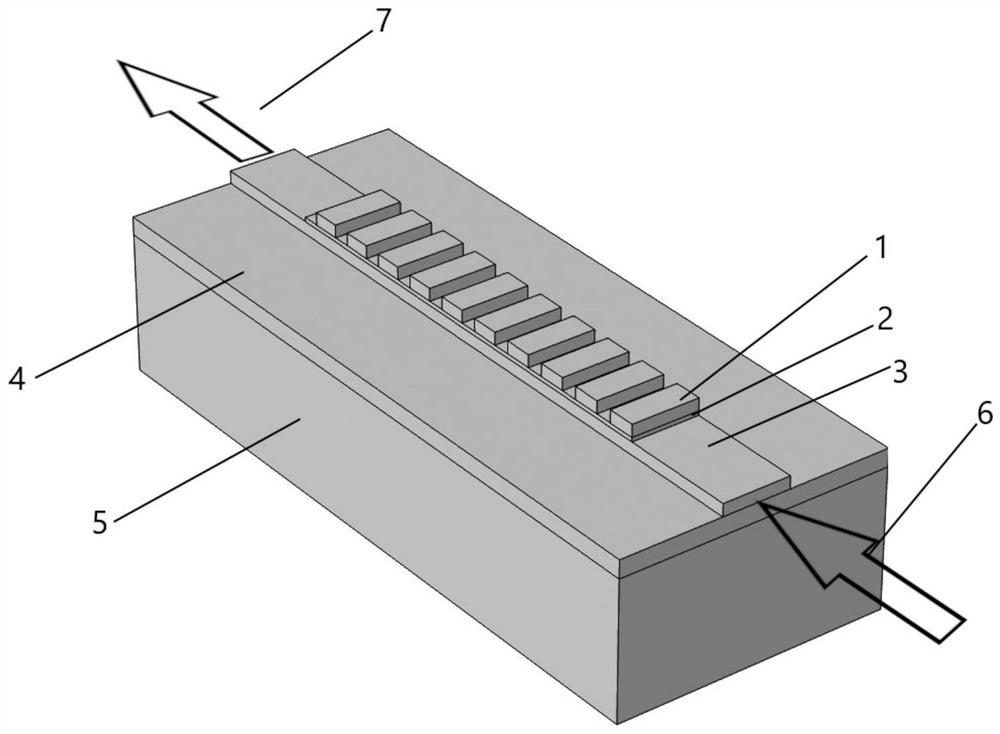
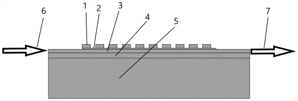
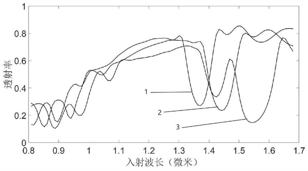
The invention discloses a switching type optical waveguide device based on a phase change material, which comprises a grating structure, an optical film enhancement layer, a ridge structure, a film structure and a substrate structure. The film structure is arranged on the substrate structure, the ridge structure is arranged in the middle of the upper surface of the film structure, the optical film enhancement layer is arranged on the ridge structure, and the grating structure is arranged on the optical film enhancement layer. A mode wave enters one end surface of the optical waveguide device, passes through a waveguide, and is emitted from the other end surface of the optical waveguide device. By means of the mode, a silicon waveguide can be covered with the material to form a composite waveguide structure, optical signal propagation can be switched among different states by switching the phase state of a phase change material, and a time division multiplexing function and a wavelength division multiplexing function are achieved at the same time by means of one structure.

Description

technical field [0001] The invention relates to the design field of micro-nano optical devices, in particular to a switch-type optical waveguide device based on phase-change materials. Background technique [0002] With the rapid development of optical communication technology, big data processing technology and micro-nano photonics technology and people's urgent need for the miniaturization of optical components and the integration of optical systems, the research, design and preparation of multifunctional micro-nano optical devices has become an important issue in the academic field. As a hotspot of widespread concern in the industry and the industry, optical components with various functions continue to emerge. The spectral selector selects a specific wavelength light source within the working band and cuts off incident light of other wavelengths. The main structure of a traditional optical filter is to vapor-deposit multiple dielectric layers with high and low refractiv...

Claims


Application Information

Patent Timeline
Patent Type & Authority Applications(China)
IPC IPC(8): G02F1/313
CPCG02F1/3133G02F1/3138
Inventor 郑分刚张桂菊王锐吕元帅
Owner 上海交大平湖智能光电研究院
Learn More