
Bendable rigid circuit board and preparation method thereof

A circuit board and rigid technology, applied in the field of bendable rigid circuit board and its preparation, can solve the problems of high production and processing costs, inconvenient use, cumbersome design process, etc.

Inactive Publication Date: 2021-04-23
万奔电子科技股份有限公司
View PDF4 Cites 0 Cited by
  • Summary
  • Abstract
  • Description
  • Claims
  • Application Information

AI Technical Summary

Problems solved by technology

[0003] Although there are many types and quantities of rigid circuit boards at present, there are still some problems in the existing printed circuit boards, which bring some inconvenience to the use
[0004] The printed rigid circuit board is relatively fragile due to material limitations. When installing the rigid circuit board, due to the limitation of the installation position, it needs to be bent. The conventional design will consider the design of the rigid-flex board. This design process is cumbersome. , the production and processing costs are high, and there are many types of special materials selected

Method used


Image

  • Bendable rigid circuit board and preparation method thereof
  • Bendable rigid circuit board and preparation method thereof
  • Bendable rigid circuit board and preparation method thereof

Examples


Embodiment 1

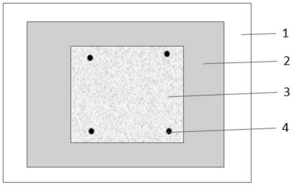
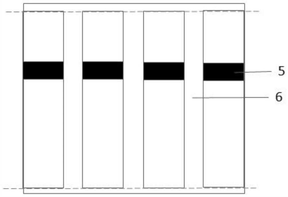
[0034] Such as Figure 1-2 As shown, a bendable rigid circuit board includes an intermediate core board arranged in the middle, copper foil layers arranged on both sides of the intermediate core board, and an environmentally friendly solder resist layer arranged outside the copper foil layer. The rigid circuit board is provided with There is a blind slot 5, and the rigid circuit board is provided with an inner slot 6 in the vertical direction of the blind slot 5.

[0035] Further, the blind groove 5 passes through the middle core board, the copper foil layer on the upper layer of the middle core board and the environmental protection solder resist layer on the upper layer of the copper foil layer, and does not pass through the copper foil layer on the lower layer of the middle core board and the environmental protection solder resist layer on the lower layer of the copper foil layer. solder layer.

[0036] Further, the intermediate core board is composed of resin glue and fib...

Embodiment 2

[0050] The difference between this embodiment and embodiment 1 is:

[0051] The intermediate core board is composed of resin glue and fibers, the fibers are a mixture of organic fibers and inorganic fibers, and the mixing ratio of organic fibers and inorganic fibers is 1:3.

[0052] The organic fiber is a mixture of high-density polyethylene and cycloolefin copolymer elastomer fiber, graphene-modified nylon fiber, and semi-carbonized cellulose, and the mixing ratio is 3:2:1.

[0053] The inorganic fiber is a mixture of glass fiber, asbestos fiber and ceramic fiber, and the mixing ratio is 3:1:2.

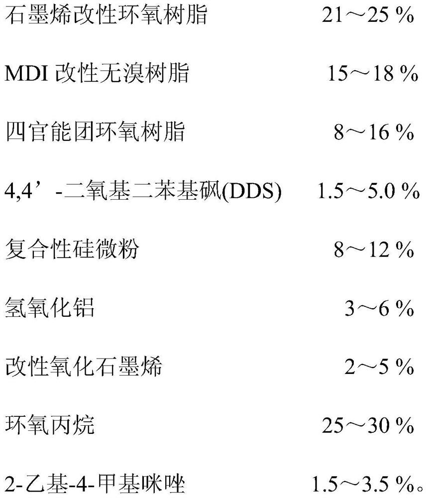
[0054] Further, the resin glue includes the following composition raw materials in weight percentage:

[0055]

[0056]

[0057] A method for preparing a bendable rigid circuit board. The preparation method is based on a preparation system. The preparation system includes a hot press machine, a forming machine and a numerically controlled milling machine. The forming machine inc...

Embodiment 3

[0066] The difference between this embodiment and embodiment 1, 2 is:

[0067] The intermediate core board is composed of resin glue and fibers, the fibers are a mixture of organic fibers and inorganic fibers, and the mixing ratio of organic fibers and inorganic fibers is 1:5.

[0068] The organic fiber is a mixture of high-density polyethylene and cycloolefin copolymer elastomer fiber, graphene-modified nylon fiber, and semi-carbonized cellulose, and the mixing ratio is 4:2:1.

[0069] The inorganic fiber is a mixture of glass fiber, asbestos fiber and ceramic fiber, and the mixing ratio is 4:1:3.

[0070] Further, the resin glue includes the following composition raw materials in weight percentage:

[0071]

[0072]

[0073] A method for preparing a bendable rigid circuit board. The preparation method is based on a preparation system. The preparation system includes a hot press machine, a forming machine and a numerically controlled milling machine. The forming machin...


PUM


Abstract

The invention relates to a bendable rigid circuit board and a preparation method thereof. The rigid circuit board comprises a middle core plate, copper foil layers arranged at two sides of the middle core plate and environment-friendly solder mask layers arranged at the outer sides of the copper foil layers, wherein the rigid circuit board is provided with a blind groove, an inner groove is formed in the rigid circuit board in the perpendicular direction of the blind groove, and the blind groove penetrates through the middle core plate, the copper foil layers and the environment-friendly solder mask layers on one side. The blind groove is formed in the rigid printed circuit board, so that the rigid printed circuit board has a bending function and meets the requirements of part of flexible boards; a thinner connecting part is arranged, so that the rigid circuit board can adapt to a smaller space in the mounting process, and the circuit board and the equipment have a better overlap ratio; when the structure is installed, installation of a special-shaped position can be met through a small gap, and installation and fixation of the rigid circuit board are facilitated through a clamping structure of the blind groove and an equipment installation position; and the blind groove structure is formed, so that wiring harnesses and devices can be assembled through an installation channel, the layout space is compressed, and a small size is formed.

Description

technical field [0001] The invention relates to the technical field of circuit board design, and more precisely relates to a bendable rigid circuit board and a preparation method thereof. Background technique [0002] The names of circuit boards include ceramic circuit boards, alumina ceramic circuit boards, aluminum nitride ceramic circuit boards, aluminum substrates, high-frequency boards, thick copper boards, impedance boards, soft and hard boards, ultra-thin circuit boards, printed circuit boards, etc. The circuit board makes the circuit miniaturized and intuitive, and plays an important role in the mass production of fixed circuits and optimizing the layout of electrical appliances. [0003] Although there are many kinds and quantities of the current rigid circuit boards, there are still certain problems in the existing printed circuit boards, which bring certain inconvenience to the use. [0004] The printed rigid circuit board is relatively fragile due to material li...

Claims


Application Information

Patent Timeline
Patent Type & Authority Applications(China)
IPC IPC(8): H05K1/02H05K3/00H05K3/28C08L63/00
CPCH05K1/02H05K3/00H05K3/282C08L63/00C08K2003/2227C08L2205/035C08K13/06C08K3/042C08K3/36C08K3/22C08K7/14C08K7/12C08K7/04
Inventor 李金贵
Owner 万奔电子科技股份有限公司
Learn More