Flue gas desulfurization process for miniature industrial gas-fired boiler

A technology for industrial gas and desulfurization process, applied in the field of flue gas desulfurization process, can solve the problems of high investment cost, difficult to handle desulfurization by-products, and difficult to handle micro-industrial gas furnace desulfurization process

Active Publication Date: 2021-04-27
ZHEJIANG TUNA ENVIRONMENTAL SCI & TECH
View PDF7 Cites 7 Cited by
  • Summary
  • Abstract
  • Description
  • Claims
  • Application Information

AI Technical Summary

Problems solved by technology

[0004] The purpose of the present invention is to provide a flue gas desulfurization process for miniature industrial gas boilers in order to solve the above problems, which solves the difficulties in the desulfur

Method used


Image

  • Flue gas desulfurization process for miniature industrial gas-fired boiler
  • Flue gas desulfurization process for miniature industrial gas-fired boiler
  • Flue gas desulfurization process for miniature industrial gas-fired boiler

Examples


Embodiment 1

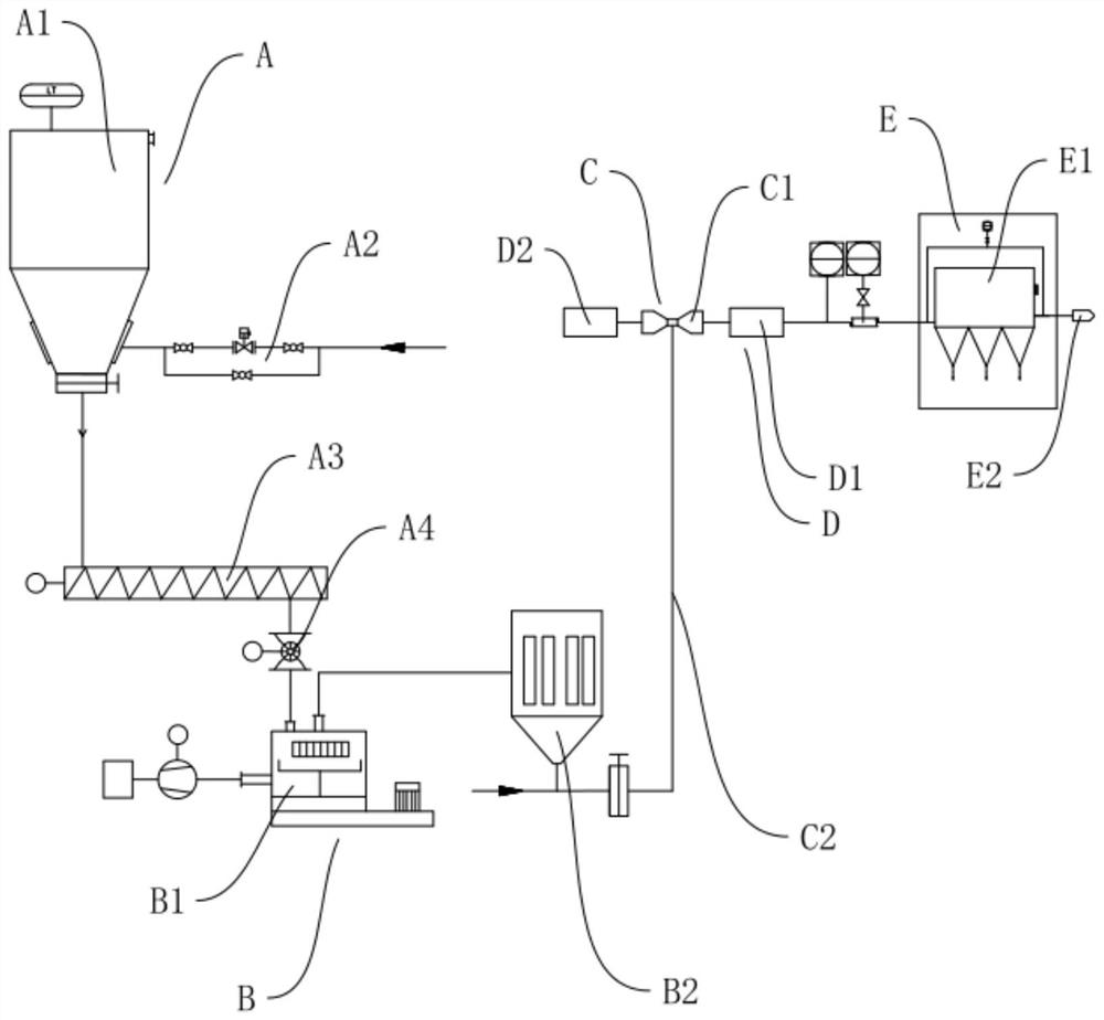
[0045] This implementation discloses a flue gas desulfurization system for micro-industrial gas-fired boilers, please refer to figure 1 As shown, it includes desulfurization agent storage system A, desulfurization agent grinding system B, dry powder injection system C, mixing system D and dust removal system E.

[0046] Desulfurizer storage system A includes desulfurizer storage bin A1, pneumatic conveying device A2, screw feeder A3 and weighing device A4, desulfurizer storage bin A1 is used to store baking soda granule desulfurizer, and pneumatic conveying device A2 passes through the pipeline Unicom desulfurizer storage bin A1 and screw feeder A3 can transport the baking soda particles in the desulfurizer storage bin A1 to the screw feeder A3, the end 24 of the screw feeder A3 is connected with the weighing device A4, through the screw feeder A3 The output baking soda granules are weighed by the weighing device A4 to realize the feeding accuracy of the baking soda granules a...

Embodiment 2

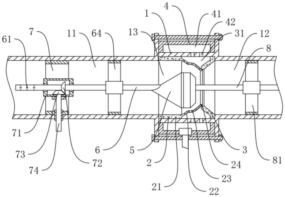
[0057] This implementation discloses another flue gas desulfurization system for micro-industrial gas-fired boilers. On the basis of Embodiment 1, refer to figure 2 As shown, the injection device C1 in the flue gas desulfurization system is further optimized.

[0058] The injection device C1 includes a mixing tube 1, and the two ends of the mixing tube 1 are respectively connected to the flue gas input pipe D2 by connecting the input pipe 11 and the output pipe 12. The mixing pipe 1 is provided with a necking pipe 2, and the necking pipe 2 includes equal-diameter Section 21 and necking section 22, the outer diameter of the equal-diameter end is consistent with the inner diameter of the mixing tube 1, the necking section 22 extends toward the output pipe 12 side, and the diameter gradually decreases;

[0059] The mixing tube 1 is also provided with a trumpet-shaped necking ring 3, the necking ring 3 is located on one side of the output pipe 12, the outer diameter of the large ...

Embodiment 3

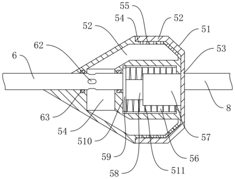
[0071] This implementation discloses another flue gas desulfurization system for micro-industrial gas-fired boilers. On the basis of Embodiment 2, refer to Figure 3-Figure 5 As shown, the injection device C1 in the flue gas desulfurization system is further optimized.

[0072] The flow limiting plug 5 mainly includes two parts, a plug body 51 and a sliding sleeve 52. The inside of the plug body 51 is provided with a pressure stabilizing chamber 54, and the outer periphery of the plug body 51 is provided with a number of stabilizing holes 55, and the stabilizing holes 55 connect the stabilizing chamber 54 communicates with the inner cavity of the mixing tube 1, the middle position of the plug body 51 is the outer cylindrical section 53, and the pressure stabilizing hole 55 is located on the cylindrical section 53; one end of the stabilizing tube 6 extends into the stabilizing chamber 54 and is provided with an air outlet 62. The other end of the voltage regulator tube 6 is loc...


PUM


Abstract

The invention discloses a flue gas desulfurization process for a miniature industrial gas-fired boiler, belonging to the technical field of flue gas desulfurization. According to key points of a technical scheme in the invention, the flue gas desulfurization process adopts a flue gas desulfurization system to desulfurize flue gas and comprises the following steps: inputting high-temperature flue gas led out after denitration through a flue gas input pipe, and spraying ultrafine sodium bicarbonate powder into the flue gas; mixing the sprayed dry powder with high-temperature flue gas to form mixed flue gas, decomposing the ultrafine sodium bicarbonate powder at high temperature, and absorbing and purifying sulfur dioxide and other acidic media in the flue gas; allowing the mixed flue gas to enter a mixing reactor for mixing, and enabling sulfur dioxide and other acid media in the flue gas to further make full contact for a chemical reaction so as to be absorbed and purified; and allowing the absorbed and purified flue gas to enter a dust removal system, and filtering and eliminating powdery particles in the mixed flue gas. The flue gas desulfurization process of the invention overcomes the problems that a miniature industrial gas furnace desulfurization process has difficulty in treatment, a traditional process system is complex, investment cost is high, desulfurization byproducts are difficult to treat and the like.

Description

technical field [0001] The invention relates to the technical field of flue gas desulfurization, more specifically, it relates to a flue gas desulfurization process for micro industrial gas boilers. Background technique [0002] Sulfur-containing pollutants are one of the main pollutants in the flue gas of industrial gas-fired boilers. At present, the main desulfurization method used in industrial gas-fired boilers is sodium-alkali desulfurization. Sodium-alkali desulfurization will produce sodium sulfite and sodium sulfate solutions, and waste liquid treatment is more difficult. ; and the sodium sulfate in the waste liquid will enter the atmosphere with the mist, causing secondary pollution; the sodium-alkali method is a wet desulfurization method, which will produce white smoke and rain. The facility covers a large area, the system is complicated, and the investment cost is high. It is generally applicable It is used in large industrial boiler systems, not suitable for use...

Claims


Application Information

Patent Timeline
IPC IPC(8): B01D53/83B01D53/50B01D53/40B01D46/02F23J15/00F23J15/02
CPCB01D53/83B01D53/508B01D53/40B01D46/02F23J15/003F23J15/02F23J15/025B01D2251/304B01D2251/606B01D2258/0283Y02A50/20
Inventor 赵博李敬东赖文锋周伟陈小利陈洪剑黄关火
Owner ZHEJIANG TUNA ENVIRONMENTAL SCI & TECH
Why Eureka
Try Eureka