Pyrolysis gas separation system with purification function and utilization method

A separation system and cracking gas technology, applied in the field of cracking and separation, can solve the problems of high energy consumption, low cooling capacity, large investment in cracking gas separation process, etc.

Active Publication Date: 2021-04-27
CHINA PETROLEUM & CHEM CORP +1
View PDF4 Cites 1 Cited by
  • Summary
  • Abstract
  • Description
  • Claims
  • Application Information

AI Technical Summary

Problems solved by technology

However, no matter what kind of separation process is used, if the rectification method is used to separate light components such as methane, it is necessary to use a cold box to provide a lower cooling capacity, which requires a large investment and high energy consumption.
In addition, to obtain polymer-grade ethylene products and polymer-grade propylene products, the number of required equipment and energy consumption are relatively large
[0005] For refineries without ethylene production facilities nearby, if the saturated resources are cracked and the cracked gas is separated by traditional cryogenic separation methods, the return on investment will be low and the energy consumption will be high
[0006] Therefore, it is urgent to develop a separation method and utilization of cracked gas to reduce the problems of large investment and high energy consumption in the cracked gas separation process.

Method used


Image

  • Pyrolysis gas separation system with purification function and utilization method
  • Pyrolysis gas separation system with purification function and utilization method
  • Pyrolysis gas separation system with purification function and utilization method

Examples


Embodiment 1

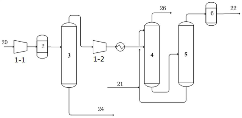
[0077] use as figure 1 A kind of pyrolysis gas separation system shown comprises: compressor (compressor front section 1-1, compressor rear section 1-2); 2 purification system; 3 weight-removing tower; 4 absorption tower; 5 desorption tower; 6 carbon Two hydrogenation reactors;

[0078] The weight removal tower is operated with two towers, namely a high pressure weight removal tower and a low pressure weight removal tower.

[0079] The compressor sections are connected to the purification system 2 and the high-pressure weight removal tower in sequence, and then to the absorption tower 4. The tank of the high-pressure de-weighting tower is connected to the low-pressure de-weighting tower, and after the top of the low-pressure de-weighting tower is connected to the rear section 1-2 of the compressor, it is connected to the cooler and the gas-liquid separation tank, and the gas phase outlet of the gas-liquid separation tank is connected to the absorption tower 4. The liquid pha...

Embodiment 2

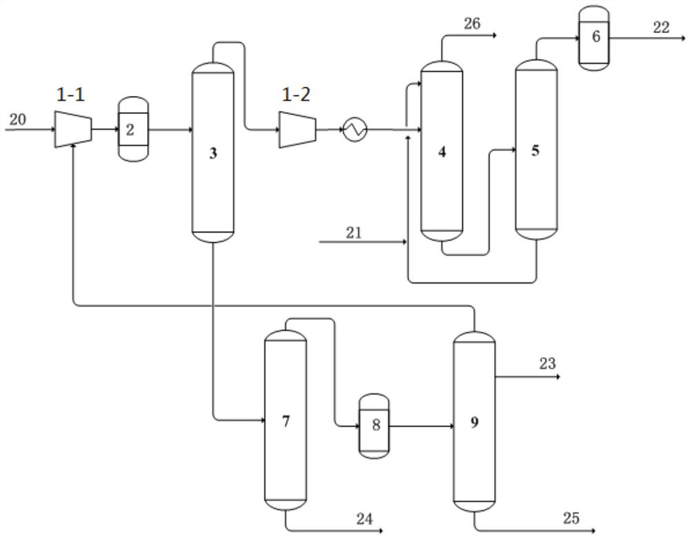
[0101] A cracking gas separation system, comprising: compressor (compressor front section 1-1, compressor rear section 1-2); purification system 2; weight removal tower 3; absorption tower 4; desorption tower 5; Device 6; Depropanizer 7; C3 hydrogenation reactor 8; Propylene rectification tower 9.

[0102] The compressor sections are connected to the purification system 2 and the high-pressure weight removal tower in sequence, and then to the absorption tower 4. The tank of the high-pressure de-weighting tower is connected to the low-pressure de-weighting tower, and after the top of the low-pressure de-weighting tower is connected to the rear section 1-2 of the compressor, it is connected to the cooler and the gas-liquid separation tank, and the gas phase outlet of the gas-liquid separation tank is connected to the absorption tower 4. The liquid phase outlet of the gas-liquid separation tank is connected to the upper part of the high-pressure de-weighting tower, the top of the...


PUM


Abstract

The invention discloses a pyrolysis gas separation system with a purification function and a separation method. The system comprises a compressor, a purification system, a heavy component removal tower, an absorption tower, a desorption tower and a C2 hydrogenation reactor, the purification system and the de-heavy tower are sequentially connected between the compressor sections, the top of the de-heavy tower is connected with the compressor rear section and then connected with the absorption tower, and the tower kettle of the absorption tower is connected with the desorption tower; the top of the desorption tower is connected with the C2 hydrogenation reactor and then connected with the outside, and the bottom of the desorption tower is connected with the upper part of the absorption tower. The system and the method have the characteristics of low investment, low energy consumption and remarkable benefit.

Description

technical field [0001] The invention relates to the technical field of cracking and separation, and furthermore, relates to a cracked gas separation system with purification and a utilization method. Background technique [0002] A large amount of tail gas will be produced in the process of oil refining and chemical production, some of which, such as tail gas produced by catalytic cracking, thermal cracking, delayed coking, hydrocracking and other production processes, contain a lot of carbon 2 and carbon 3 components, especially some tail gas In , the ethane / propane content is relatively high. At present, the C2C3 concentrated gas recovered from the tail gas of the refinery is mainly sent to different sections of the ethylene plant to increase the production of ethylene propylene. However, for refineries without ethylene production facilities nearby, the concentrated gas The whereabouts is a major problem, resulting in the C2C3 resources in the dry gas not being fully util...

Claims


Application Information

Patent Timeline
Patent Type & Authority Applications(China)
IPC IPC(8): C07C7/00C07C7/11C07C11/04C07C11/06C07C9/08C10G70/06
CPCC07C7/005C07C7/11C10G70/041C10G70/06C10G70/04C10G70/02C10G2400/20C10G2400/28C10G2400/26C07C11/04C07C11/06C07C9/08
Inventor 李东风罗淑娟李琰李春芳邹弋舒展
Owner CHINA PETROLEUM & CHEM CORP
Why Eureka
Try Eureka