
Micro-fiber high-energy implantation facility for manufacturing three-dimensional reinforced carbon fiber composite material

A technology of reinforcing fibers and microfibers, which is applied in the field of microfiber high-energy implantation equipment, can solve the problems of laminate performance degradation, laminate structure damage, fiber curling and fracture, etc., achieve high reinforcement density, small matrix damage, and increase reinforcement density and quality effects

Active Publication Date: 2021-04-30
ZHEJIANG UNIV
View PDF8 Cites 1 Cited by
  • Summary
  • Abstract
  • Description
  • Claims
  • Application Information

AI Technical Summary

Problems solved by technology

The fiber diameter of the traditional Z-pin reinforcement technology is generally 0.2mm to 0.6mm, and the volume fraction ratio is generally between 2% and 5%. The implantation of Z-pin improves the interlayer performance of the laminate, but the toughening process is easy to cause Problems such as fiber deflection, fiber curl fracture, and formation of fat-rich areas will cause damage to the original structure of the laminate to a certain extent, resulting in a decrease in the in-plane performance of the laminate

Method used


Image

  • Micro-fiber high-energy implantation facility for manufacturing three-dimensional reinforced carbon fiber composite material
  • Micro-fiber high-energy implantation facility for manufacturing three-dimensional reinforced carbon fiber composite material
  • Micro-fiber high-energy implantation facility for manufacturing three-dimensional reinforced carbon fiber composite material

Examples


Embodiment Construction

[0053] In the following description, many specific details are set forth in order to fully understand the present invention, but the present invention can also be implemented in other ways different from those described here, therefore, the present invention is not limited to the specific embodiments disclosed below limit. The orientation words "up", "down", "left" and "right" involved in this article are set based on the corresponding drawings. It can be understood that the appearance of the above orientation words does not limit the protection of the present invention. scope.

[0054] Embodiments of the present invention are described in detail below, examples of which are shown in the drawings, wherein the same or similar reference numerals designate the same or similar elements or elements having the same or similar functions throughout. The embodiments described below by referring to the figures are exemplary and are intended to explain the present invention and should n...


PUM


Abstract

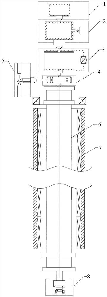
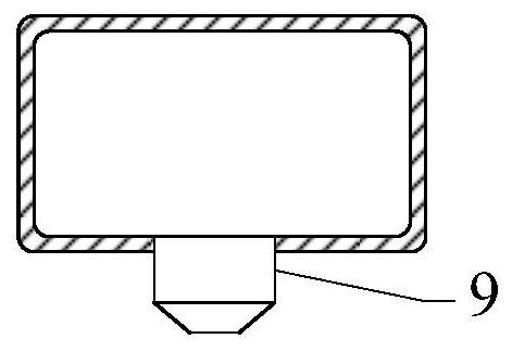
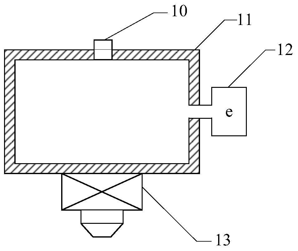
The invention discloses a micro-fiber high-energy implantation facility for manufacturing a three-dimensional reinforced carbon fiber composite material. The facility comprises a micro reinforced fiber feeding module, a micro reinforced fiber directional arrangement module, a micro reinforced fiber electrification module, a micro reinforced fiber accelerator injection module, a vacuum generation device module, a high-voltage electrostatic acceleration module, an accelerator bunching module and a micro reinforced fiber leading-out control module. According to the micro-fiber high-energy implantation facility, large-scale micro reinforced fibers which are subjected to charging treatment and meet the target charge-to-mass ratio magnitude requirement serve as a high-energy implanted fiber source, a high-voltage electrostatic acceleration electric field is adopted to accelerate and energize the array type large-scale micro reinforced fibers which are uniformly and directionally arranged, and therefore the speed and the energy of the array type large-scale micro reinforced fibers can meet the implantation requirements; and the micro reinforced fibers are injected into a two-dimensional laminated structure prepreg target reinforced area through the output kinetic energy of the micro reinforced fibers, and manufacturing of the three-dimensional reinforced carbon fiber composite material is achieved.

Description

technical field [0001] The invention relates to the field of carbon fiber composite material implantation equipment, in particular to a microfiber high-energy implantation equipment for manufacturing three-dimensional reinforced carbon fiber composite material. Background technique [0002] With the development of aerospace technology, carbon fiber reinforced composite laminate structures have been widely used due to their many advantages. However, due to mechanical connection and other design requirements, the laminates need to be opened, causing delamination and stress concentration at the edge of the hole, which reduces the overall strength of the structure and becomes an important cause of failure. It is of great significance to reduce the interface damage caused by opening holes by enhancing the interlayer properties. [0003] In the prior art, the application documents of publication numbers CN 110027304 A and CN 111583309A all adopt Z-pin continuous implantation tech...

Claims


Application Information

Patent Timeline
Patent Type & Authority Applications(China)
IPC IPC(8): B29C70/30B29C70/54
CPCB29C70/30B29C70/54B29C70/14B29C70/24B29C70/081
Inventor 柯映林李江雄朱伟东王青王晗
Owner ZHEJIANG UNIV
Learn More