Microwave methods for converting hydrocarbon-based waste materials into oil and gas fuels

A technology that transforms into microwave cavities, applied in the field of plastic pyrolysis system and plastic waste pyrolysis system, can solve the elusive problems of energy efficiency and sustainability

Pending Publication Date: 2021-04-30
瑞西纳吉公司
View PDF22 Cites 2 Cited by
  • Summary
  • Abstract
  • Description
  • Claims
  • Application Information

AI Technical Summary

Problems solved by technology

However, energy efficiency and demonstrable sustainability have been elusive

Method used


Image

  • Microwave methods for converting hydrocarbon-based waste materials into oil and gas fuels
  • Microwave methods for converting hydrocarbon-based waste materials into oil and gas fuels
  • Microwave methods for converting hydrocarbon-based waste materials into oil and gas fuels

Examples


Embodiment Construction

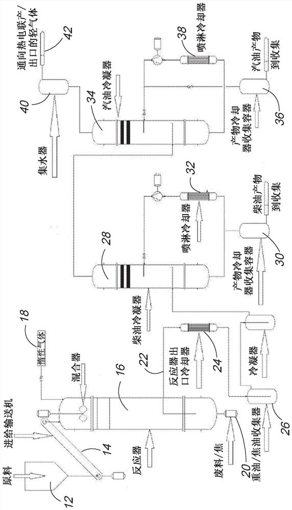
[0027] first reference Figure 1A , wherein there is shown a new and improved method and system for converting hydrocarbon-based waste into hydrocarbon fuels, the system generally indicated herein at 10 in this schematic diagram.

[0028] Figure 1A is a highly schematic level process flow diagram showing the main functional components of the system, highlighting the main sub-component systems. When ready for processing, in one embodiment, material is fed from material hopper 12 into mechanical conveyor 14 at ambient temperature while maintaining an optimal feed rate. In another embodiment, the raw material may be fed into the conveyor at an elevated melt temperature, also maintaining an optimal feed rate. When feeding at elevated temperatures, an extruder is employed to ensure a smooth flow of material into the reactor. Furthermore, in an embodiment, the heated feedstock is cooled to a temperature between 30°C and 50°C prior to introduction into the reactor to reduce the pos...


PUM


Abstract

A portable, sustainable, and efficient system and apparatus for breaking down processed solid plastic waste and other polymer-based feedstock into fuel oil, sustainable energy, carbon char, and other useful products. With minor modifications, biomass can also be treated. Distributed microwave heating sources and mechanical mixing effectively mix heat in a highly insulated reactor that protects the microwave components, makes fast pyrolysis possible, and thereby enables scaling down to compact and highly portable systems. Products include diesel, gasoline, propane, butane, and char. Product materials are distributed using tight temperature control and mechanical routing.

Description

technical field [0001] The present invention relates most generally to systems for converting solid waste streams of specific materials into commercially valuable chemical commodities, and more particularly to plastic waste pyrolysis systems, and still more particularly to the use of microwave energy to convert comminuted waste Energy-efficient plastic pyrolysis systems that heat plastics to useful and separable by-products, including fuels. Background technique [0002] It is known to use thermal decomposition techniques, more specifically pyrolysis techniques, to convert plastic waste into combustible fuels. However, energy efficiency and demonstrable sustainability have been elusive. Also, because the conversion of certain materials may produce heavy metals as well as sulfur and nitrogen containing compounds, it is a system imperative to design systems that minimize the generation of unsafe by-product compounds. However, with increased efficiency and increased portabili...

Claims


Application Information

Patent Timeline
Patent Type & Authority Applications(China)
IPC IPC(8): B01J19/12C10B19/00H05B6/64
CPCC10B19/00H05B6/784H05B6/6491H05B2206/045C10K3/023C10B53/07C10G1/10B01J19/0013B01J19/002B01J19/126B01J4/001C10B31/02C10L3/08C10L3/12C10L2200/0423C10L2200/0446C10L2200/0469H05B6/647
Inventor 布莱恩·鲍尔詹森·唐纳泰勒·斯波特弗兰克·梅休A·J·麦金尼斯马修·莱斯克里斯托弗·卡迪纳尔汤姆·格里尔
Owner 瑞西纳吉公司
Why Eureka
Try Eureka