
Supercharged engine and ammonia fuel hybrid power generation system

A supercharged engine and power generation system technology, applied in the field of ammonia decomposition, can solve the problems of energy waste, low fuel utilization rate, poor combustion characteristics, etc.

Inactive Publication Date: 2021-05-07
FUZHOU UNIV ASSET MANAGEMENT CO LTD
View PDF7 Cites 9 Cited by
  • Summary
  • Abstract
  • Description
  • Claims
  • Application Information

AI Technical Summary

Problems solved by technology

[0005] Therefore, the technical problem to be solved by the present invention is to overcome the poor combustion characteristics of ammonia in the air in the prior art and cause the traditional pure ammonia internal combustion engine to need pure oxygen as a combustion aid or to completely decompose ammonia, and the fuel cell using ammonia as fuel The low fuel utilization rate of the system causes energy waste and other defects, so as to provide a supercharged engine and ammonia fuel hybrid power generation system

Method used


Image

  • Supercharged engine and ammonia fuel hybrid power generation system
  • Supercharged engine and ammonia fuel hybrid power generation system
  • Supercharged engine and ammonia fuel hybrid power generation system

Examples


Embodiment 1

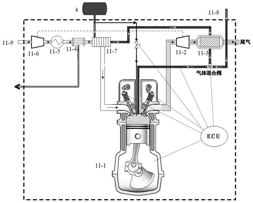
[0047] This embodiment provides a supercharged engine 11, such as figure 1 shown, including,

[0048] The internal combustion engine 11-1 communicates with the liquid ammonia storage tank 4, and the liquid ammonia in the liquid ammonia storage tank is transported to the internal combustion engine 11-1 as fuel;

[0049] The membrane separation module 11-7, the first gas enters the membrane separation module 11-7 after being compressed and boosted by the first compressor 11-6, cooled by the intercooler 11-5, and the first gas is separated to obtain nitrogen-enriched gas and Oxygen-enriched gas; nitrogen-enriched gas is discharged, and the oxygen-enriched gas enters the vaporizer 11-4, exchanges heat with liquid ammonia from the liquid ammonia storage tank 4, makes the liquid ammonia gasify, and the oxygen-enriched gas enters the internal combustion engine 11-1 after heat exchange Combustion, the liquid ammonia after heat exchange enters the ammonia decomposition reaction compon...

Embodiment 2

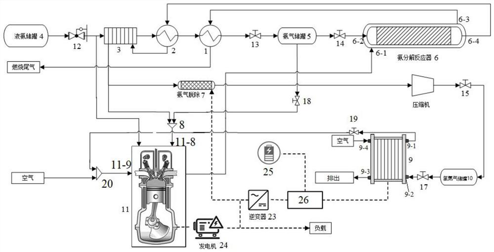
[0055] This embodiment provides an ammonia fuel hybrid power generation system, such as figure 2 As shown, it includes the supercharged engine 11 provided in Embodiment 1, and also includes a liquid ammonia storage tank 4, a first pressure reducing valve 12, an evaporator 3, a second heat exchange device 2, and a first heat exchange device 1 connected in sequence. and ammonia gas storage tank 5; wherein, the liquid ammonia in the liquid ammonia storage tank 4 enters the ammonia decomposition reactor 6 after passing through the evaporator 3, the second heat exchange device 2, the first heat exchange device 1 and the ammonia gas storage tank 5 successively The ammonia decomposition reaction takes place in the ammonia decomposition reactor, the first regulating valve 13 is used to control the flow of ammonia, the sixth regulating valve 14 is used to control the flow of ammonia entering the ammonia decomposition reactor, and the ammonia storage tank is used to store ammonia. When...

Embodiment 3

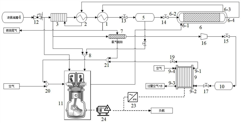
[0063] This embodiment provides an ammonia fuel hybrid power generation system, such as Figure 4 As shown, it includes the supercharged engine 11 provided by Embodiment 1, and also includes a liquid ammonia storage tank 4, an evaporator 3, a first heat exchange device 1 and an ammonia gas storage tank 5 connected in sequence, wherein the first regulating valve 13 is used for Control the flow of ammonia gas;

[0064] The ammonia fuel hybrid power generation system also includes,

[0065] The ammonia decomposition reactor 6 is communicated with the booster engine 11; the ammonia decomposition reaction is provided with a tail gas input port 6-1, which is used to transport the tail gas produced by the booster engine 11 to the ammonia decomposition reactor to provide heat for the ammonia decomposition reaction, Then the tail gas is exported to the first heat exchange device 1 through the tail gas output port 6-3, and enters the evaporator 3 after exchanging heat with the raw mate...


PUM


Abstract

The invention belongs to the technical field of ammonia decomposition, and particularly relates to a supercharged engine and an ammonia fuel hybrid power generation system. The supercharged engine comprises an internal combustion engine, a membrane separation assembly and an ammonia decomposition reaction assembly, wherein first gas is compressed and then enters the membrane separation assembly, nitrogen-rich gas and oxygen-rich gas are obtained through separation, the oxygen-rich gas exchanges heat with liquid ammonia from a liquid ammonia storage tank through a vaporizer assembly, then the oxygen-rich gas enters the internal combustion engine, and the liquid ammonia exchanges heat with the oxygen-rich gas through a vaporizer and then enters the ammonia decomposition reaction assembly to be subjected to ammonia decomposition reaction; tail gas generated by the internal combustion engine enters a turbine to do work, and the turbine drives a first compressor to compress the first gas; the first gas enters the membrane separation assembly after being compressed, oxygen-nitrogen separation or hydrogen-oxygen-nitrogen separation is achieved, the oxygen-rich gas enters the internal combustion engine, and the combustion characteristic is improved; and meanwhile, the oxygen-rich gas and the liquid ammonia exchange heat in the vaporizer, the temperature of the oxygen-rich gas is reduced, the temperature of the liquid ammonia is increased, the liquid ammonia is gasified into gas, and the inflation coefficient of the internal combustion engine is increased.

Description

technical field [0001] The invention belongs to the technical field of ammonia decomposition, and in particular relates to a booster engine and an ammonia-fuel hybrid power generation system. Background technique [0002] Ammonia is not only an important inorganic chemical product, but also has unique advantages as a hydrogen carrier. Easy to liquefy, with pungent smell, high ignition point and non-toxic at low concentration, high hydrogen storage density, mature production, storage and transportation technology, and no carbon emissions in the hydrogen production process, it is an efficient, clean and safe hydrogen storage carrier . [0003] Because ammonia has a high ignition point and slow flame propagation speed in the air, it is usually necessary to mix it with other flammable fuels when using ammonia as a fuel for internal combustion engines. If only pure ammonia is used as fuel, it is usually necessary to decompose it into hydrogen and nitrogen gas or use pure oxygen...

Claims


Application Information

Patent Timeline
IPC IPC(8): F02M21/02F01N5/02F01N5/04H01M8/04089H01M8/04082H01M8/0612B01D53/22
CPCB01D53/22B01D2053/221F01N5/02F01N5/04F02M21/0206F02M21/0218F02M21/0227H01M8/04089H01M8/04201H01M8/0618Y02E60/50Y02T10/12Y02T10/30
Inventor 江莉龙林立罗宇陈崇启蔡国辉
Owner FUZHOU UNIV ASSET MANAGEMENT CO LTD
Learn More