Middle-section cement clinker fine crushing device

A cement clinker and fine crushing technology, applied in the field of cement clinker processing, can solve the problems of single particle size and inability to realize online adjustment

Pending Publication Date: 2021-05-14
山东博研粉体技术装备有限公司
View PDF1 Cites 0 Cited by
  • Summary
  • Abstract
  • Description
  • Claims
  • Application Information

AI Technical Summary

Problems solved by technology

[0004] Aiming at the deficiencies of the prior art, the purpose of the present invention is to solve the technical problem that the particle s

Method used


Image

  • Middle-section cement clinker fine crushing device
  • Middle-section cement clinker fine crushing device
  • Middle-section cement clinker fine crushing device

Examples


Embodiment 1

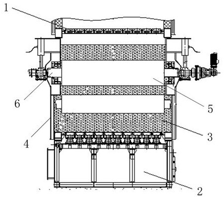
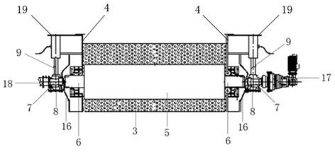
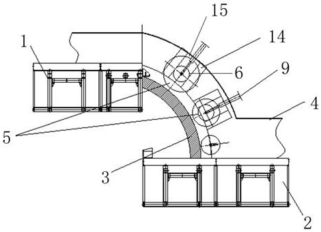
[0037] like figure 1 As shown, a middle-section cement clinker fine crushing device includes a front section grate bed 1, a rear section grate bed 2 and an outer shell 4, and a grinding bed 3 is arranged between the front section grate bed 1 and the rear section grate bed 2 , the upper surface of the grinding bed 3 is provided with a roller device, and the front section grate bed 1, the rear section grate bed 2, the grinding bed 3 and the roller device are all located inside the outer shell 4, and the roller device and the grinding bed 3 A hydraulic system is arranged between them, and the hydraulic system is symmetrically arranged on both sides of the outer shell 4 and is perpendicular to the grinding bed 3. The hydraulic system includes a hydraulic cylinder 9, and the rear end of the hydraulic cylinder 9 is connected to the external shell 4 through a connecting plate 19. The housing 4 is fixedly connected, and the front end of the rod of the hydraulic cylinder 9 is fixedly c...

Embodiment 2

[0045] Same as Example 1, the difference is: as Figure 4 As shown, the gap adjustment device is a screw device, and the screw device is symmetrically arranged on both sides of the outer casing 4. The screw device includes a screw 10, and the screw 10 is fixedly connected to the outer casing 4 through a connecting plate 19. One end of the connecting plate 19 is provided with a round hole 11, and the screw rod 10 is sleeved in the round hole 11. One end of the screw rod 10 is fixedly connected with the top surface of the bearing seat 8, and the other end is threadedly connected with a nut 12. The nut 12 Located on the upper surface of the connecting plate, a spring 13 is sleeved on the outside of the screw rod 10 , one end of the spring 13 is connected to the bottom surface of the connecting plate, and the other end is connected to the top surface of the bearing seat 8 .

[0046] Working principle: Cement clinker enters the grinding bed 3 through the front grate bed 1, and the ...

Embodiment 3

[0048] Same as Example 1, the difference is that: the grinding bed 3 is a slope surface at a certain angle with the front section grate bed 1, the surface of the grinding bed 3 is a wear-resistant layer, and the front section grate bed 1 and the rear section The grate bed 2 has a certain vertical height difference, and the range of the vertical height difference is 1.5-2.5m.


PUM


Abstract

A middle-section cement clinker fine crushing device relates to the technical field of cement processing, aims to solve the technical problem of adjustable material crushing size, and adopts the technical scheme as follows: the middle-section cement clinker fine crushing device comprises a front-section grate bed, a rear-section grate bed and an outer shell, a grinding bed is arranged between the front-section grate bed and the rear-section grate bed; and a roller device is arranged on the upper surface of the grinding bed, the front-section grate bed, the rear-section grate bed, the grinding bed and the roller device are all located in the outer shell, and a gap adjusting device is arranged between the roller device and the grinding bed. Compared with an existing middle-section clinker crusher, materials can be crushed into smaller particles, high-pressure grinding is achieved, and the yield and efficiency are improved; and energy conservation and consumption reduction are realized, the finished product granularity is adjustable on line, the thermal efficiency of a rotary kiln is improved, the calcination of materials in the kiln is facilitated, and the power consumption of clinker grinding is reduced.

Description

technical field [0001] The invention relates to the technical field of cement clinker processing, in particular to a middle-stage cement clinker fine crushing device. Background technique [0002] Cement clinker is a semi-finished product obtained by using limestone, clay, and iron as the main raw materials, which are prepared into raw meal in an appropriate proportion, burned until part or all of it is melted, and cooled. During the cement firing process, the high-temperature cement clinker needs to be cooled by the cooler before entering the middle crusher or the end crusher. The particle size of the crushed material is generally controlled to 30mm. Compared with the end crushing, the middle roller crushing has improved Cooler efficiency, reducing the clinker temperature out of the cooler. The working principle of the middle stage roller crushing mainly depends on the gravity of the cement clinker falling into the roller crushing and the friction force with the rollers, s...

Claims


Application Information

Patent Timeline
IPC IPC(8): B02C4/10B02C4/32B02C4/44B02C4/28B02C23/02
CPCB02C4/10B02C4/286B02C4/32B02C4/44
Inventor 张伟业张磊余中杰周丹丁冉
Owner 山东博研粉体技术装备有限公司
Why Eureka
Try Eureka