Microwave differential sensor based on substrate-integrated waveguide reentrant cavity and microfluidic technology

A substrate-integrated waveguide and resonant cavity technology, applied in the field of sensors, can solve the problems that the process cannot obtain a good transmission response, reduce the sensitivity of small disturbances, and it is difficult to solve the problem of feeding, and achieves compact structure, reduced manufacturing costs, and good electromagnetic properties. The effect of isolation

Active Publication Date: 2022-04-19
SOUTHWEST UNIV
View PDF15 Cites 0 Cited by
  • Summary
  • Abstract
  • Description
  • Claims
  • Application Information

AI Technical Summary

Problems solved by technology

In the existing differential microwave sensors based on the principle of resonance, there are basically the following deficiencies: the coupling between the two sensing elements reduces the sensitivity to small disturbances; most of the resonators are combined in the horizontal direction; in order to The method of expanding the distance between components to avoid coupling between sensing elements makes the relative size of the overall structure larger and makes the structure not compact enough
[0004] In addition, simply placing the two resonant cavities used as reference and sensing vertically is difficult to solve the feeding problem, because the common coplanar waveguide feeder line cannot provide equal power to the two cavities at the same time longitudinally, which will cause the two cavities themselves to be unstable. Balanced, and the direct use of stripline, the actual process can not get a better transmission response

Method used


Image

  • Microwave differential sensor based on substrate-integrated waveguide reentrant cavity and microfluidic technology
  • Microwave differential sensor based on substrate-integrated waveguide reentrant cavity and microfluidic technology
  • Microwave differential sensor based on substrate-integrated waveguide reentrant cavity and microfluidic technology

Examples


Embodiment Construction

[0039] In order to better describe the design process and purpose, the present invention will be further described below in conjunction with the embodiments and accompanying drawings:

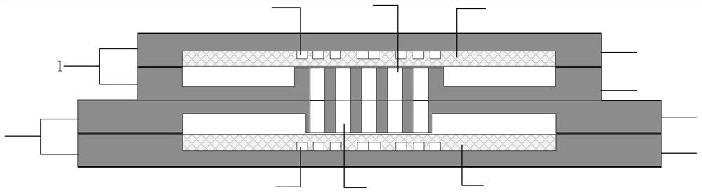
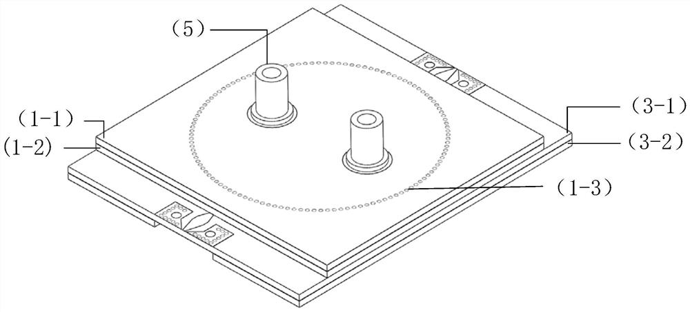
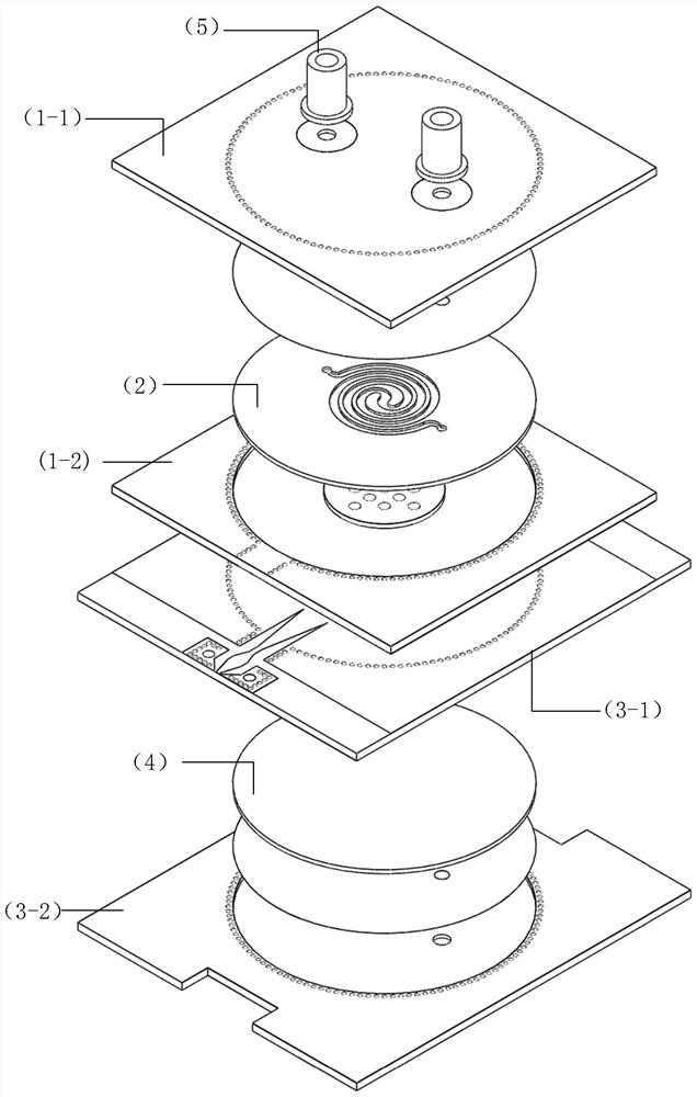
[0040] Such as figure 1 As shown in Figure 7(a) and Figure 7(b), the microwave differential sensor based on substrate-integrated waveguide re-entrant cavity and microfluidic technology proposed by the present invention includes two substrate-integrated waveguide re-entrant cavity and two The chip is embedded in a microfluidic chip placed in the resonant cavity.

[0041] The resonant cavity (1) is composed of an upper cover plate (1-1) and a lower bottom plate (1-2). Both the upper cover plate (1-1) and the lower bottom plate (1-2) include a three-layer structure, which are respectively a top metal layer, an intermediate dielectric layer and a bottom metal layer. The resonance cavity (3) is composed of an upper cover plate (3-1) and a lower bottom plate (3-2). Both the upper cover plate (3-1)...


PUM

PropertyMeasurementUnit
widthaaaaaaaaaa
lengthaaaaaaaaaa
widthaaaaaaaaaa

Abstract

A microwave differential sensor based on a substrate-integrated waveguide dual-entry resonant cavity and microfluidic technology, comprising two resonant cavities and a microfluidic chip; both cavities are composed of a superimposed upper cover plate and a lower bottom plate. Both the upper cover plate and the middle dielectric layer of the lower bottom plate contain several metal through holes to connect the top layer and the bottom metal layer, and the bottom metal layer of the second layer board and the top layer metal of the third layer board are etched with feed lines with gradual changes. There is an annular groove inside each cavity, and a capacitor column is formed in the middle, corresponding to the chip microchannel. The two cavities serve as sensing and reference resonant cavities respectively. The sensor combines two reentrant resonators ingeniously vertically, utilizes the naturally existing metal walls between the resonant cavities and the special excitation method, and combines the advantages of highly concentrated electric field of the resonant cavity and microfluidic chips that can precisely control microfluidics to form A microwave differential sensor with compact structure, free from interference by factors such as temperature and humidity, independent components, which can be used for liquid dielectric characterization.

Description

technical field [0001] The invention belongs to the field of sensors, and specifically relates to a microwave differential sensor combined with resonant cavity and microfluidic technology. Background technique [0002] With the rapid development of microwave technology in many industries (such as military, medical, food, chemical and meteorology, etc.), various types of radio frequency microwave devices have been gradually developed and applied. The electromagnetic properties of magnetic media materials greatly affect the performance parameters of equipment devices, so the research on the electromagnetic properties of magnetic media materials is very important. [0003] There are many methods used to measure the dielectric constant, which are mainly divided into resonance method and non-resonance method. The most typical method in the resonance method is the resonant cavity method. Most material characterization sensors convert the change in the dielectric constant of the s...

Claims


Application Information

Patent Timeline
Patent Type & Authority Patents(China)
IPC IPC(8): G01R27/26G01R33/12G01N22/00H01P5/00H01P7/06B01L3/00
CPCG01R27/2617G01R27/2658G01R27/2664G01R27/2635G01R33/1253G01N22/00H01P7/065H01P5/00B01L3/5027B01L2300/12
Inventor 黄杰付灵龙
Owner SOUTHWEST UNIV
Why Eureka
Try Eureka