Charging/discharging device and charging/discharging system for electric vehicle

A charge-discharge device and charge-discharge technology, applied in the direction of charge/discharge current/voltage regulation, electric vehicles, electrical devices, etc., can solve the problem of increased copper loss on the low-voltage side of the secondary side, non-optimal OBC charging efficiency, and large reactive power Loss and other issues

Pending Publication Date: 2021-05-14
DELTA ELECTRONICS INC
View PDF7 Cites 5 Cited by
  • Summary
  • Abstract
  • Description
  • Claims
  • Application Information

AI Technical Summary

Problems solved by technology

Among them, since the LV output side adopts uncontrolled rectification, the energy cannot flow in both directions, and the energy cannot be reversely precharged to the output capacitor. figure 1 (shown in the dotted line box) to precharge the capacitor Cbus on the bus side of the motor M
[0004] However, for the traditional three-port magnetic integration scheme, when designing, it is limited by the capacitance withstand voltage of the capacitor Cbus1 on the primary bus side. ) The turn ratio of the transformer primary winding and the secondary high-voltage side winding must be close to 1 or less than 1
Although this design can ensure the safety of the bus voltage, the charging efficiency of the OBC is not optimal at this time.
Moreover, since the voltage on the low-voltage side is usually 9 to 16V, if the number of turns on the primary side is too low in actual design, such as 25 turns, when the bus voltage is 420V and the number of turns on the low-voltage side of the secondary side is 1 turn, it will be converted to low-voltage The voltage on the low-voltage side is 16.8V. If you want to control the voltage on the low-voltage side to 13.5V at this time, reactive power control will be introduced. Even if the output power on the low-voltage side is small, there will be a large reactive power loss.
Therefore, on the one hand, the existing design cannot optimize the charging efficiency of the OBC; on the other hand, if the design is improper, the low-voltage side will introduce a large reactive current
[0005] In addition, when the electric vehicle is in the power supply running (Running) mode, the primary side is in the no-load state, and the equivalent gain of the high-voltage side of the OBC secondary side to the primary side will be very high, considering the dynamic situation when the high-voltage side runs independently from the low-voltage side , the bus voltage has the risk of rushing up, which will cause damage to the bus capacitor
In this mode, in order to reduce the bus voltage, one method is to switch the circuit on the high-voltage side of the secondary side to work as an asymmetric half-bridge. At this time, the circuit on the high-voltage side will have a large resonance current, and the conduction of the switch tube The loss increases, and the low-voltage side of the secondary side will introduce a large phase shift angle, the reactive current will increase, the copper loss of the low-voltage side of the secondary side will increase, and the efficiency will decrease

Method used


Image

  • Charging/discharging device and charging/discharging system for electric vehicle
  • Charging/discharging device and charging/discharging system for electric vehicle
  • Charging/discharging device and charging/discharging system for electric vehicle

Examples


Embodiment Construction

[0043] Example embodiments will now be described more fully with reference to the accompanying drawings. Example embodiments may, however, be embodied in many forms and should not be construed as limited to the embodiments set forth herein; rather, these embodiments are provided so that this disclosure will be thorough and complete, and will fully convey the concept of example embodiments to those skilled in the art. The same reference numerals in the drawings denote the same or similar structures, and thus their detailed descriptions will be omitted.

[0044] When introducing elements / components / etc. described and / or illustrated herein, the terms "a", "an", "the", "said" and "at least one" are used to mean that there are one or more elements / components / etc. The terms "comprising", "including" and "having" are used in an open inclusive sense and mean that there may be additional elements / components / etc. besides the listed elements / components / etc. Relative terms such as "up...


PUM


Abstract

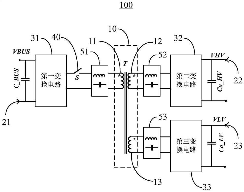
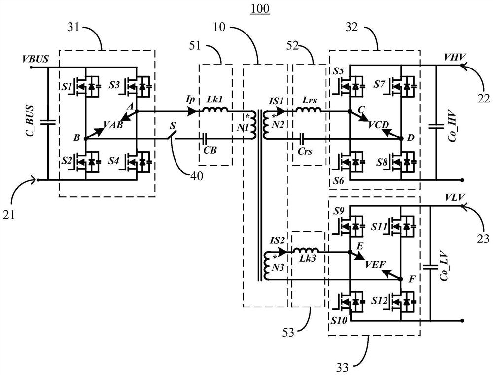
The invention provides a charging / discharging device and a charging / discharging system for an electric vehicle. The charging and discharging device comprises: a transformer which comprises a primary winding and a plurality of secondary windings, and the plurality of secondary windings at least comprise a first secondary winding and a second secondary winding; the plurality of ports that are respectively and electrically connected with a primary winding and a plurality of secondary windings of the transformer, and the plurality of ports at least comprise: a first port which is electrically connected with the primary winding through a first conversion circuit; a second port which is electrically connected with the first secondary winding through a second conversion circuit; the third port that is electrically connected with the second secondary winding through a third conversion circuit; and the first controllable switch that is connected between the first conversion circuit and the primary winding. The voltage of the first port of the charging and discharging device is a first voltage, the voltage of the second port is a second voltage, and the voltage of the third port is a third voltage.

Description

technical field [0001] The invention relates to the field of electric vehicles, in particular to a charging and discharging system and a charging and discharging device for the electric vehicle. Background technique [0002] The internal power distribution system of an electric vehicle (such as an electric vehicle) mainly involves three energy conversion units, namely: an AC / DC conversion unit that charges a high-voltage battery, that is, an on-board charging unit (On-Board-Charger, OBC); LV DC / DC conversion unit, which converts the voltage of the high-voltage battery into a low voltage, such as 12V, to supply power to low-voltage systems such as lighting and audio in the car; the DC / AC conversion unit of the drive motor system, which is the main source of driving power for electric vehicles . From the perspective of power level, the power of the on-board charging unit and the low-voltage DC / DC conversion unit is much lower than the power of the DC / AC conversion unit drivi...

Claims


Application Information

Patent Timeline
Patent Type & Authority Applications(China)
IPC IPC(8): H02J7/00B60L1/00B60L3/00
CPCH02M3/3353H02M1/008H02M3/33561H02M3/33584Y02B70/10H02M3/33573H02M3/285H02M1/0096H02M3/015H02J7/007H02M3/33592H02M7/5387H02J50/12H02M1/0058
Inventor 贾民立孙浩章进法
Owner DELTA ELECTRONICS INC
Why Eureka
Try Eureka