Passive power factor correction converter with high power factor and low output ripple

A passive power factor, power factor correction technology, applied in the direction of converting DC power input to DC power output, output power conversion device, high-efficiency power electronic conversion, etc., can solve problems such as input and output characteristic limitations, and achieve circuit reliability. High, simple control, small output ripple effect

Inactive Publication Date: 2021-05-14
SOUTHWEST JIAOTONG UNIV
View PDF2 Cites 3 Cited by
  • Summary
  • Abstract
  • Description
  • Claims
  • Application Information

AI Technical Summary

Problems solved by technology

[0004] Using the charge pump to realize the PFC function must inject a high-frequency signal, and combine the LLC resonant circuit to inject a high-frequency current source into the charge pump to realize the PFC function. However, due to the limitation of the input and output characteristics of the LLC circuit, the converter can only operate at a specific narrow input voltage. Realize the PFC function within the range

Method used


Image

  • Passive power factor correction converter with high power factor and low output ripple
  • Passive power factor correction converter with high power factor and low output ripple
  • Passive power factor correction converter with high power factor and low output ripple

Examples


Embodiment Construction

[0035]The present invention will be described in further detail below in conjunction with the accompanying drawings and specific embodiments.

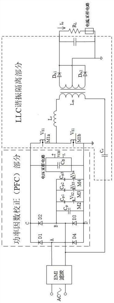
[0036] A passive power factor correction converter with high power factor and low output ripple of the present invention includes a power factor correction PFC part, a resonance isolation LLC part and a control system.

[0037] Power Factor Correction PFC section as figure 1 As shown, including rectifier bridge, charge pump capacitor network and post-stage bus capacitor.

[0038] The power supply system is connected to the rectifier bridge through the EMI filter input, the positive input terminal is connected to the diode node A, that is, the anode of D1 is connected to the cathode of D4, and the negative input terminal is connected to the diode node B, that is, the anode of D2 is connected to the cathode of D3; the positive and negative output nodes of the rectifier bridge are respectively Denoted as node C (D1 cathode and D2 cathode...


PUM


Abstract

The invention discloses a passive power factor correction converter with high power factor and low output ripple. The converter comprises a power factor correction PFC part, a resonance isolation LLC part and a control system. The PFC part comprises a rectifier bridge, a charge pump capacitor network and a post-stage bus capacitor; the resonance isolation LLC part comprises two power device switch tubes M1a and M1b, a resonance tank circuit and a half-bridge rectification structure; the resonant tank circuit is composed of a transformer excitation inductor Lm, a resonant capacitor Cr and a resonant inductor Lr; and the control system comprises a main circuit control system and a capacitance network control system. Based on a charge pump structure, through designing the charge pump capacitor network, the converter realizes passive power factor correction (PF >= 0.98) in a wide input voltage range, the output ripple is small (<= 2%), the circuit is of a single-stage PFC structure, the topology is simple, the size is small, the control is simple, the cost is extremely low, and the reliability is high.

Description

technical field [0001] The invention belongs to the field of switching power supplies in power electronics, in particular to a passive power factor correction converter with high power factor and low output ripple. Background technique [0002] In order to reduce the harmonic pollution of the power electronic device to the power grid, the AC-DC converter needs to have a power factor correction (Power Factor Correction, PFC) function. The traditional two-stage AC-DC converter has complicated control, large volume, and high circuit cost. Therefore, single-stage PFC converter has become a research hotspot in small and medium power applications. [0003] The active single-stage PFC converter reduces the number of components and reduces the circuit cost to a certain extent, but due to the existence of inductance in the switching circuit, the circuit volume is still large, and the output ripple of this type of circuit is large. Compared with the active single-stage PFC converter,...

Claims


Application Information

Patent Timeline
Patent Type & Authority Applications(China)
IPC IPC(8): H02M1/42H02M3/07H02M3/335H02M1/14
CPCH02M1/14H02M1/4208H02M1/4266H02M3/07H02M3/33569Y02B70/10
Inventor 杨平孙义杰彭宇圣刘湘许建平
Owner SOUTHWEST JIAOTONG UNIV
Why Eureka
Try Eureka