Workpiece ultrasonic-plasma electrolysis combined machining method and machining device

A processing method and processing device technology, which is applied in the field of plasma electrolytic composite processing method and processing device, can solve the problems of free abrasive bonding and lower processing efficiency, etc.

Active Publication Date: 2021-05-18
SOUTH UNIVERSITY OF SCIENCE AND TECHNOLOGY OF CHINA
View PDF10 Cites 2 Cited by
  • Summary
  • Abstract
  • Description
  • Claims
  • Application Information

AI Technical Summary

Problems solved by technology

However, since nickel alloy materials with thermal barrier coatings are multilayer materials, although ultrasonic machining has good processing characteristics for ceramic-based thermal barrier coating parts, it is easy to cause free metal parts for metal-based parts with good toughness. Abrasives are bonded to the metal surface, reducing processing efficiency, so ultrasonic processing of nickel alloy materials with thermal barrier coatings also has certain limitations

Method used


Image

  • Workpiece ultrasonic-plasma electrolysis combined machining method and machining device
  • Workpiece ultrasonic-plasma electrolysis combined machining method and machining device
  • Workpiece ultrasonic-plasma electrolysis combined machining method and machining device

Examples


Embodiment 1

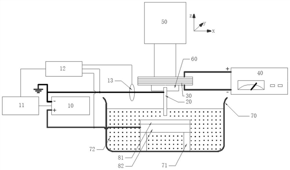
[0042] This embodiment provides a processing device, figure 1 It is a schematic diagram of the processing device, which includes an electrolytic machining power supply system, a tool electrode 20, an ultrasonic vibration unit and an electrolytic unit, and the workpiece including the non-metallic layer 81 and the metal layer 82 is processed by the processing device. The electrolytic machining power supply system includes an electrolytic machining power supply 10, a function generator 11, an oscilloscope 12, and a power probe 13. These parts are electrically connected, the positive pole of the electrolytic machining power supply 10 is used to connect with the metal layer 82, and the negative pole of the electrolytic machining power supply 10 is connected to the metal layer 82. The tool electrode 20 is connected, and the tool electrode 20 is rod-shaped. The ultrasonic vibration unit includes an ultrasonic vibrator 30 and an ultrasonic processing power supply 40 , and the positive...

Embodiment 2

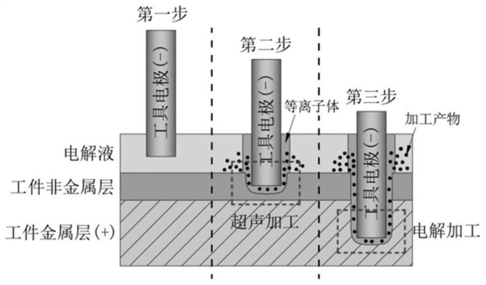
[0054] This embodiment provides a method of processing a workpiece using the processing device provided in Embodiment 1. The workpiece includes a non-metallic layer and a metal layer arranged in sequence. The processing method includes the following steps. The principle is as follows: image 3 Shown:

[0055] Initial stage (first step): providing an electrolyte between the non-metallic layer and the tool electrode. In this embodiment, specifically, the end of the tool electrode away from the ultrasonic vibrator and the workpiece are immersed in the electrolyte.

[0056] The metal layer is connected to the positive pole of the electrolytic machining power supply, the tool electrode is connected to the negative pole of the electrolytic machining power supply, and a DC voltage above 50V is applied between the metal layer and the tool electrode. The applied high voltage causes the tool electrode to be quickly surrounded by hydrogen bubbles generated by electrolysis, the resistance...


PUM


Abstract

The invention discloses a workpiece ultrasonic-plasma electrolysis combined machining method and a machining device. The machining method comprises the following steps that an electrolyte is provided between a non-metal layer and a tool electrode; a metal layer is connected with the anode of an electrolytic machining power supply, the tool electrode is connected with the cathode of the electrolytic machining power supply, and direct-current voltage is applied between the metal layer and the tool electrode; and the tool electrode moves relative to the non-metal layer from the side, far away from the metal layer, of the non-metal layer, and ultrasonic waves are guided to the non-metal layer. According to the method, firstly, the surface of the non-metal layer is machined through the ultrasonic waves guided to the non-metal layer, and in the ultrasonic machining process, plasma generated through induction can promote solution circulation of ultrasonic machining, so that products of ultrasonic machining are rapidly discharged out of a machining area. And after the non-metal layer is machined, the metal layer is exposed, so that ultrasonic electrolysis parallel processing is carried out on the metal layer.

Description

technical field [0001] The present application relates to the technical field of material processing, in particular to an ultrasonic-plasma electrolytic composite processing method and processing device for workpieces. Background technique [0002] With the development of aviation and aerospace technology, the operating temperature requirements of hot end components are getting higher and higher, which has reached the limit of the use of superalloys and single crystal materials. For example, the blades at the front and rear ends of the aero-engine combustor, the heated nozzles and impellers of the gas turbine, their working temperature reaches above 1000°C, which is close to or exceeds the limit service temperature of the base material (usually high-temperature nickel alloy, heat-resistant about 1075°C). In this extremely harsh high-temperature environment, the material is prone to high-temperature oxidation and thermal stress deformation, which affects the performance of th...

Claims


Application Information

Patent Timeline
Patent Type & Authority Applications(China)
IPC IPC(8): B23H5/08B23H7/38
CPCB23H5/08B23H7/38Y02T50/60
Inventor 赵永华詹顺达何德树
Owner SOUTH UNIVERSITY OF SCIENCE AND TECHNOLOGY OF CHINA
Why Eureka
Try Eureka