Boundary layer PM2.5 detection method

A detection method and boundary layer technology, applied in separation methods, chemical instruments and methods, measuring devices, etc., can solve problems such as high cost, difficulty in obtaining high-precision measurement results, and high cost of use

Active Publication Date: 2021-05-18
北方大贤风电科技(北京)有限公司
View PDF7 Cites 1 Cited by
  • Summary
  • Abstract
  • Description
  • Claims
  • Application Information

AI Technical Summary

Problems solved by technology

[0003] At present, the detection of PM2.5 in the atmosphere includes the methods of optical ray absorption and micro-vibration balance, all of which need to effectively collect PM2.5 particles, and the boundary layer in the atmosphere has a certain height and is in the process of change. The distribution of matter is different from the atmosphere on the surface. The use of optical radar is limited by the sampling area and produces high costs. It is difficult to obtain high-precision measurement results by using remote sensing satellites, which weakens the accuracy of PM2.5 detection data.
[0004] There are also some technical solutions about the PM2.5 detection method in the boundary layer in the prior art. For example, a Chinese patent with the application number 2012103843325 discloses an automatic reflection of the PM2.5 mass concentration based on a sun photometer and a laser radar. Algorithm, first use the sun photometer to obtain the optical thickness of the entire layer of atmospheric aerosol based on the sun photometer, use the echo signal of the lidar, after correcting the distanc

Method used


Image

  • Boundary layer PM2.5 detection method
  • Boundary layer PM2.5 detection method
  • Boundary layer PM2.5 detection method

Examples


Embodiment approach

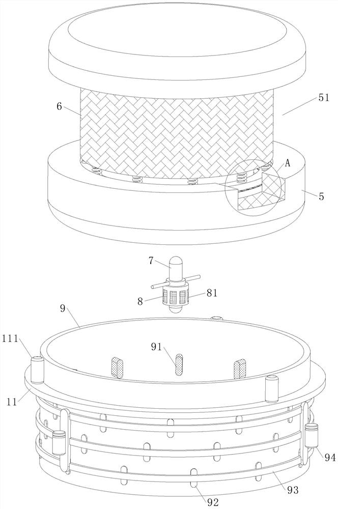
[0046] As an embodiment of the present invention, the airtight cylinder 9 is also provided with combs 91, the combs 91 are intermittently distributed on the inner wall of the airtight cylinder 9, and the tops of the combs 91 are in contact with the surface of the air filter 6; A roller motor 111 is also provided between the ring 11 and the airtight cylinder 9, and the hoop ring 11 makes the airtight cylinder 9 rotate through the roller motor 111; During the process, it will be blocked on the air filter 6, and when the pollutant content is high, it will affect the passability of PM2.5 in the air filter 6, thereby weakening the accuracy of its detection; Combing 91, in cooperation with the drum motor 111 in the hoop 11, makes the airtight tube 9 wrapped on the surface of the air filter 6 rotate, and drives the comb 91 to sweep over the surface of the air filter 6, so that the airtight tube 9 attached to the air filter 6 The large particle pollutants on the surface of 6 are separ...


PUM


Abstract

The invention belongs to the technical field of air detection and relates to a boundary layer PM2.5 detection method. The method comprises the steps of boundary layer division, floating ball setting, suspended area detection, data set coupling and floating ball recovery. A floating ball comprises a power mechanism, a collecting assembly, information modules and a controller. Due to the flowing characteristics of the atmosphere of a boundary layer, the distribution of pollutants is in a disordered state, sampling by adopting an optical radar is limited by regions, a high-precision measurement result is difficult to obtain by utilizing a remote sensing satellite, and the accuracy of PM2.5 detection is weakened; therefore, the range of the divided boundary layer is set through the floating ball, the power mechanism in the floating ball is suspended at different heights in the boundary layer and is used for operation of the collection assembly; PM2.5 is detected for multiple times at different heights in the boundary layer by using a bogie and a hollow pipe in a sampling cylinder, and real-time transmission is carried out on the measured data between the information modules, so that the application effect of the boundary layer PM2.5 detection method is improved.

Description

technical field [0001] The invention relates to the technical field of air detection, in particular to a boundary layer PM2.5 detection method. Background technique [0002] The atmospheric boundary layer is close to the surface of the earth and is mainly affected by the earth-atmosphere interaction and air pollution. Turbulent vertical exchange is its remarkable feature. As the air layer where air pollution mainly occurs, the boundary layer has a significant impact on the diffusion and accumulation of air pollutants; PM2.5 in pollutants refers to particulate matter in the ambient air with an aerodynamic equivalent diameter less than or equal to 2.5 microns. It can be suspended in the air for a long time. The higher its concentration in the air, the more serious the air pollution, and the longer the residence time in the atmosphere and the longer the transportation distance, the more impact it has on human health and the quality of the air environment. Big. [0003] At pre...

Claims


Application Information

Patent Timeline
IPC IPC(8): G01N15/06G01N5/02G01N1/24G01N1/26B01D46/00
CPCG01N15/0606G01N5/02G01N1/24G01N1/26B01D46/681B01D46/76
Inventor 潘涛余浩南郑昕丁谊
Owner 北方大贤风电科技(北京)有限公司
Why Eureka
Try Eureka