
Rotating equipment and using method

A technology of rotating equipment and rotating devices, applied to chemical instruments and methods, mixers with rotating stirring devices, mixers, etc., can solve the problems of poor control of distribution and mixing, large mass of rotating rotors, and high energy consumption of motors, etc. problems, to achieve the effect of high good rate, high production efficiency, and reduce production costs

Pending Publication Date: 2021-05-25
FUZHOU UNIV
View PDF9 Cites 2 Cited by
  • Summary
  • Abstract
  • Description
  • Claims
  • Application Information

AI Technical Summary

Problems solved by technology

However, this equipment has the following disadvantages: (1) The mass of the rotating rotor used in industrialization is large, and the energy consumption of the motor is large; (2) The rotor is easily damaged when it is in contact with solids when it rotates at high speed; (3) The rotor used in the biological reaction process is easy to damage microorganisms. Damage occurs; (4) The material is unevenly distributed in the rotating device, especially when the fluid viscosity is high; (5) When it comes to multiple feeds, the distribution and mixing of each feed in the bed cannot be well controlled

Method used


Image

  • Rotating equipment and using method
  • Rotating equipment and using method
  • Rotating equipment and using method

Examples


Embodiment 1

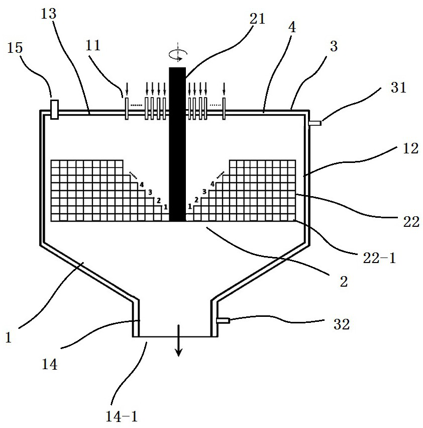
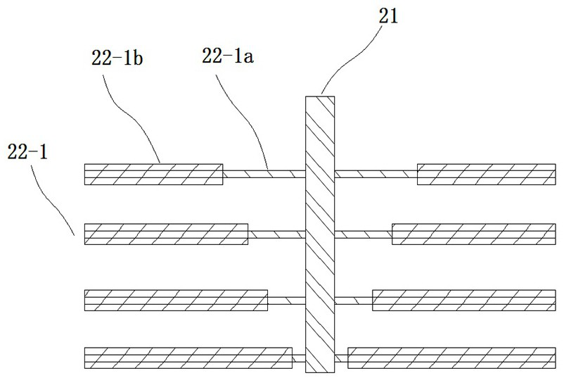
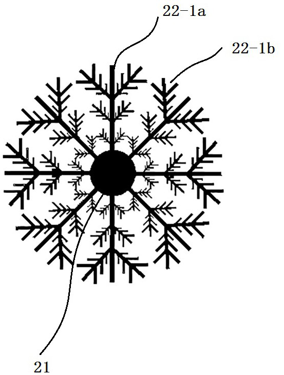
[0036] refer to Figure 1 to Figure 3 , a kind of rotating equipment, comprises reaction box shell 1, the rotating device 2 that is placed in reaction box shell 1, the motor that provides kinetic energy to rotating device 2 and the vacuum pump that is connected with reaction box shell, and described rotating device 2 includes vertically arranged The rotating shaft 21 and the dispersing component 22 installed on the rotating shaft 21 to form a fractal geometric structure. The dispersing assembly 22 includes four dispersing layers 22-1 installed on the rotating shaft 21, and each dispersing layer includes eight radially arranged support rods 22-1a and dispersing elements 22-1b on the support rods . A protruding portion is formed at one end of each dispersing element 22-1b close to the rotating shaft 21, and the protruding portion on the upper dispersing layer is farther away from the rotating shaft 21 than the protruding portion on the lower dispersing layer. The rotating devi...

Embodiment 2

[0042] like Figure 4 The difference between this embodiment shown and Embodiment 1 is that the dispersing element 22-1b of this embodiment is a brush piece of flexible polymer material, and its effect is the same as that of the above embodiment. Brush blades are more suitable for stirring harder materials.

Embodiment 3

[0044] A method for using a rotating device, comprising the following steps:

[0045] S1, start the motor connected to the rotating shaft 21, so that the rotating device 2 is idling; start the vacuum pump connected to the vacuum pump interface 15 to pump and decompress the inside of the reaction box shell 1, so that the inside of the reaction box shell reaches the vacuum requirement during the reaction ;

[0046] S2. Inject high-temperature or low-temperature circulating liquid into the thermal interlayer 4 through the jacket shell circulating liquid inlet 32 ​​and flow out through the jacket shell circulating liquid outlet 31, and continue to circulate so that the temperature in the reaction tank shell 1 reaches the standard;

[0047] S3. Finally, different materials are poured into the reaction box shell 1 through each material inlet 11, so that each material falls into the active area where the protrusion of a dispersion element 22-1b in the reaction box shell is located, ...


PUM


Abstract

The invention discloses rotating equipment and a using method, and belongs to the technical field of rotating equipment. The rotating equipment comprises a box shell and a rotating device arranged in the box shell; the rotating device comprises a vertically arranged rotating shaft and a dispersion assembly which is mounted on the rotating shaft and is of a fractal geometric structure; and the dispersion assembly comprises a plurality of dispersing layers, and each dispersing layer at least corresponds to one material inlet. Compared with the prior art, the weight and cost of the rotor can be greatly reduced, the rotor is not prone to damage when making contact with solid during high-speed rotation, and damage to microorganisms can be greatly reduced when the rotor is used in the biological reaction process; when multi-strand material feeding and high-viscosity fluid are involved, the distribution uniformity of the materials in the rotating device can be greatly improved, the distribution and mixing of each strand of feeding in the rotating bed are controlled, and the heat transfer, mass transfer and reaction efficiency of the materials in the rotating device is greatly improved.

Description

technical field [0001] The invention belongs to the technical field of rotating equipment, and in particular relates to a rotating equipment and a use method. Background technique [0002] Process intensification has always been a hot spot in the research of chemical technology. Centrifugal field intensification is an emerging technology in the field of process intensification. It is mainly used to strengthen multiphase flow transfer and reaction processes. As the most widely used process intensification equipment in industrial production, the rotary device is specifically used in many fields such as chemical industry, biopharmaceuticals, environmental protection, light industry, etc., and has achieved good results. The supergravity technology uses a high-speed rotating device to generate a centrifugal force field that is hundreds to thousands of times stronger than gravity, so that the liquid phase forms a thinner liquid film, tiny liquid droplets and extremely fine liquid ...

Claims


Application Information

Patent Timeline
Patent Type & Authority Applications(China)
IPC IPC(8): C02F3/00B01F7/18B01F7/00B01F15/06
CPCC02F3/00B01F27/00B01F27/90B01F35/90
Inventor 严佐毅李智育郑成辉
Owner FUZHOU UNIV
Learn More