Large-view-field infrared thermal imaging optical system and application thereof
An infrared thermal imaging and optical system technology, which is applied in the optical field to achieve the effects of high spatial resolution imaging capability, high illumination uniformity, and large imaging field of view
- Summary
- Abstract
- Description
- Claims
- Application Information
AI Technical Summary
Problems solved by technology
Method used
Image

Examples
Embodiment
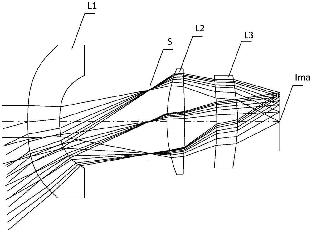
[0043] Such as Figure 1 to Figure 6 As shown, the large field of view infrared thermal imaging optical system of the present invention sequentially includes a meniscus negative power lens L1, a diaphragm S, a biconvex positive power lens L2, and a meniscus lens along the optical axis from the object plane to the image plane Ima. Positive power lens L3. Wherein, the aperture stop S provided between the meniscus negative lens L1 and the biconvex positive lens L2 is an aperture stop S.
[0044] In order to reduce the distortion and high-level aberration caused by the large-angle incident light entering the optical system, the reciprocal 1 / γ of the angular magnification of the off-axis chief ray of the meniscus-shaped negative focal power lens L1 satisfies:
[0045] 1.5≤1 / γ≤2.4.
[0046] The focal power ΦL1 of the meniscus negative focal power lens L1 and the focal power φ of the imaging optical system satisfy the following relationship:
[0047] -0.45≤φL1 / φ≤-0.30.
[0048] T...
PUM
 Abstract
Description
Claims
Application Information
 - Generate Ideas
- Intellectual Property
- Life Sciences
- Materials
- Tech Scout
- Unparalleled Data Quality
- Higher Quality Content
- 60% Fewer Hallucinations
Browse by: Latest US Patents, China's latest patents, Technical Efficacy Thesaurus, Application Domain, Technology Topic, Popular Technical Reports.
© 2025 PatSnap. All rights reserved.Legal|Privacy policy|Modern Slavery Act Transparency Statement|Sitemap|About US| Contact US: help@patsnap.com