Thoracoscopic heart failure treatment system

A treatment system and thoracoscope technology, applied in the field of medical devices, can solve the problems of uncontrollable injection volume and injection depth, large trauma in thoracotomy, inaccurate needle depth, etc., so as to reduce injection leakage, avoid blood vessel damage, shorten the The effect of surgery time

Pending Publication Date: 2021-06-01
NINGBO DIOCHANGE MEDICAL TECH CO LTD
View PDF2 Cites 6 Cited by
  • Summary
  • Abstract
  • Description
  • Claims
  • Application Information

AI Technical Summary

Problems solved by technology

[0007] The purpose of the present invention is to overcome the deficiencies of the prior art, and provide a thoracoscopic heart failure treatment system for patients with heart failure, which solves the problem of injection leakage, uncontrollable injection volume and injection depth, and needle pricking depth in the prior art. Inaccurate, insufficient operating space, limited surgical field of view, and large trauma in open thoracotomy

Method used


Image

  • Thoracoscopic heart failure treatment system
  • Thoracoscopic heart failure treatment system
  • Thoracoscopic heart failure treatment system

Examples


specific Embodiment 1

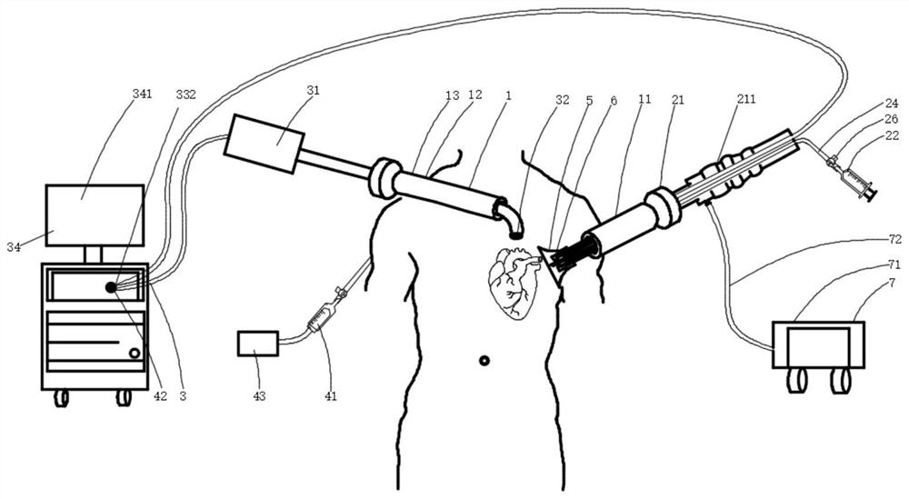
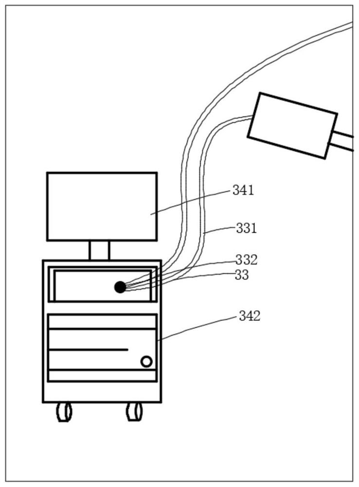
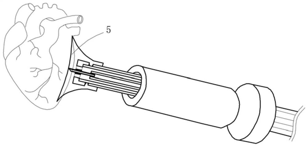
[0053] In this embodiment, taking the treatment of heart failure as an example, a thoracoscopic heart failure treatment system, such as figure 1 As shown, it includes a puncture device 1, a myocardial filling device 2, and an imaging device 3, wherein the puncture device 1 includes a first channel 11 and a second channel 12, and the first channel 11 is used to provide the myocardial filling device 2 from outside the body. The second channel 12 is used to provide a track for the imaging device 3 to enter the thoracic cavity from outside the body. The puncture device 1 is mainly used to establish a minimally invasive channel in the chest to ensure that the myocardial filling device 1 and the The imaging device 3 can smoothly enter the chest cavity, reduce the negative impact of surgical wounds, and ensure that medical devices can be used within a safe range; the myocardial filling device 2 includes an injection device 21, a filler 22, an injection needle 23 and an injection tube ...

specific Embodiment 2

[0078] In this embodiment, taking the treatment of heart failure as an example, such as figure 1 As shown, a thoracoscopic heart failure treatment system includes a puncture device 1, a myocardial filling device 2, and an imaging device 3, wherein the puncture device 1 includes a first channel 11 and a second channel 12, and the first channel 11 is used to provide a track for the myocardial filling device 2 to enter the chest cavity from outside the body, and the second channel 12 is used to provide a track for the imaging device 3 to enter the chest cavity from the outside; the myocardial filling device 2 includes an injection device 21, a filler 22 , an injection needle 23 and an injection tube 24, the injection device 21 includes an injection control device 211, the injection control device 211 is arranged on the injection tube 24, the injection control device 211 is operated, and the filler 22 is injected via The injection needle 23 is injected into the myocardial tissue; ...


PUM


Abstract

The invention relates to the field of medical instruments, in particular to a thoracoscopic heart failure treatment system which comprises a puncture device, a myocardial filling device and an imaging device. The puncture device comprises a first channel and a second channel, the first channel is used for providing a track for the myocardial filling device to enter the thoracic cavity from the outside, and the second channel is used for providing a track for the imaging device to enter the thoracic cavity from the outside; the myocardial filling device comprises an injection device, filler, an injection needle and an injection tube; the injection device comprises an injection control device, the injection control device is arranged on the injection tube, the injection control device is operated, and the filler is injected into myocardial tissue through the injection needle; the imaging device comprises an image receiving assembly, an image processing assembly and a display device, and the far-end part of the injection needle and/or the injection tube is imaged and displayed on the imaging device.

Description

technical field [0001] The invention belongs to the field of medical devices, and in particular relates to a system for treating heart failure under a thoracoscope. Background technique [0002] At present, the morbidity and mortality of heart failure are relatively high, and it is an important cause of death for most patients with cardiovascular diseases. There are nearly 23 million people in the world suffering from this disease. The full name of heart failure is heart failure, which means that due to the dysfunction of the systolic or diastolic function of the heart, the venous return blood cannot be fully excreted from the body, resulting in blood stasis in the venous system and insufficient blood supply in the arterial system, which eventually leads to cardiac circulatory system disorders. It is estimated that the incidence of acute myocardial infarction in my country is about 45 / 100,000 to 55 / 100,000, and it is still showing an upward trend. Since the development of he...

Claims


Application Information

Patent Timeline
Patent Type & Authority Applications(China)
IPC IPC(8): A61B17/34A61B90/00A61B5/00
CPCA61B17/3415A61B17/3421A61B90/37A61B5/0071A61B5/0084A61B2017/3445A61B2017/00243
Inventor 吕世文陈超李彪李佳楠陈琦杨欣金翔
Owner NINGBO DIOCHANGE MEDICAL TECH CO LTD
Why Eureka
Try Eureka