Cast-in-place concrete pile with mixing layer wrapped pile section, drill bit for pile forming and construction method

A technology for concrete and cast-in-place piles, which is applied to drill bits, earthwork drilling, sheet pile walls, etc., can solve the problems of the stress between piles and soil not being fully exerted, and the energy-saving requirements cannot be well met, so as to reduce pile formation. Cost, side resistance increase, and the effect of increasing pile end resistance

Pending Publication Date: 2021-06-04
刘守进 +1
View PDF0 Cites 1 Cited by
  • Summary
  • Abstract
  • Description
  • Claims
  • Application Information

AI Technical Summary

Problems solved by technology

[0002] Among the existing building pile foundations, cast-in-place concrete piles have strong advantages: the pile diameter is large, and the pile length can be determined according to engineering geology and design requirements, especially for engineering projects with large fluctuations in the bearing layer, the pile length The changes are large, and the application advantages are prominent. These piles are mostly cylindrical piles with the same diameter, and the stress effect between the pile and the soil has not been fully utilized, which cannot well meet the energy-saving requirements.

Method used


Image

  • Cast-in-place concrete pile with mixing layer wrapped pile section, drill bit for pile forming and construction method
  • Cast-in-place concrete pile with mixing layer wrapped pile section, drill bit for pile forming and construction method
  • Cast-in-place concrete pile with mixing layer wrapped pile section, drill bit for pile forming and construction method

Examples


Embodiment 1

[0067] Embodiment 1 Drill bit for forming piles with double leads

[0068] 1. Structure

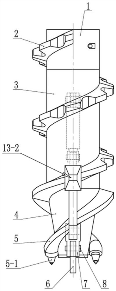
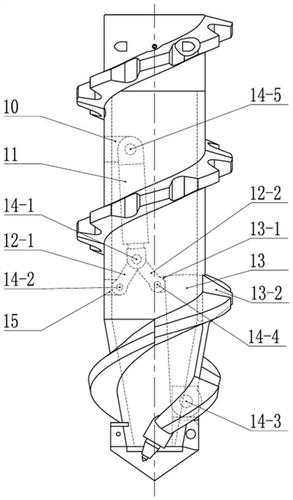
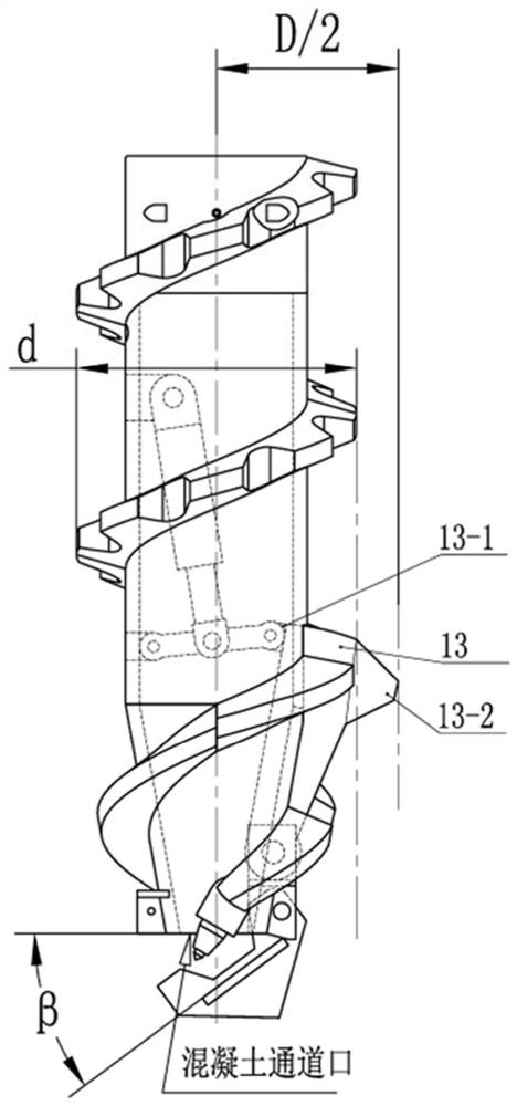
[0069] Such as Figure 1-Figure 3 As shown, a drill bit for piling with double lead, including a joint 1, a helical cylinder soil extruding blade 2, a cylinder core tube 3, a cone core tube 4, two helical cone soil extruding blades 5, a drill tip assembly Become 6, seat 7, pin 8, oil cylinder ear plate 10 and expanding diameter slide block device.

[0070] The joint 1, the cylindrical core tube 3, and the cone core tube 4 are fixed together with the axial center in turn, and the inner cavity can be used for concrete to pass through, and the spiral cylindrical extruding blade 2 is spirally wound on the outer surface of the joint 1 and the cylindrical core tube 3 , 2 identical helical cone soil-extruding blades 5 are symmetrically wound on the outer surface of the cone core tube 4, the overall outer edge of the cone core tube 4 is in the shape of a truncated cone, and the upper end of one...

Embodiment 2

[0090] Embodiment 2 Single-lead pile-forming drill bit

[0091] Such as Figure 6-Figure 8 As shown, a drill bit for single-lead pile forming includes a joint 1, a helical cylinder soil extruding blade 2, a cylinder core tube 3, a cone core tube 4, a helical cone soil extruding blade 5, a drill tip assembly Become 6, seat 7, pin 8, oil cylinder ear plate 10 and expanding diameter slide block device.

[0092] Other structures are exactly the same as in Embodiment 1, the difference is that a spiral cone soil squeezing blade 5 is provided, and a spiral cone soil squeezing blade 5 is spirally wound on the outer surface of the cone core tube 4, and the upper end and the spiral cylinder The lower ends of the earth-squeezing blades 2 are correspondingly connected. After the outer surface of the cone-shaped core tube 4 is wound with the spiral cone-shaped earth-extruding blade 5, the overall outer edge is cylindrical.

[0093] Such as Figure 9 As shown, in one embodiment, after t...

Embodiment 3

[0094] Embodiment 3 Drill bit for pile forming with single lead

[0095] Such as Figure 10-Figure 12 As shown, a drill bit for single-lead pile forming includes a joint 1, a helical cylinder soil extruding blade 2, a cylinder core tube 3, a cone core tube 4, a helical cone soil extruding blade 5, a drill tip assembly Become 6, seat 7, pin 8 and expanding diameter slide block device.

[0096] The joint 1, the cylindrical core tube 3, and the cone core tube 4 are fixed together with the axial center in turn, and the inner cavity can be used for concrete to pass through, and the spiral cylindrical extruding blade 2 is spirally wound on the outer surface of the joint 1 and the cylindrical core tube 3 1 piece of spiral cone soil extrusion blade 5 is helically wound on the outer surface of the cone core tube 4, the upper end is connected with the lower end of the spiral cylinder soil extrusion blade 2 correspondingly, and the lower end of the spiral cone soil extrusion blade 5 is ...


PUM


Abstract

The invention relates to a cast-in-place concrete pile with a mixing layer wrapped pile section, a drill bit for pile forming and a construction method. The cast-in-place concrete pile with the mixing layer wrapped pile section is composed of a pile body section and a pile bottom section; the pile body section at least comprises one mixing layer wrapped pile section; and the mixing layer wrapped pile section is arranged at the bottom end and/or the middle portion and/or the top end of the pile body section. According to the mixing layer wrapped pile section, the periphery of a pile body of a foundation pile section is wrapped by a mixing layer which has a certain thickness and is formed by a mixture formed by stirring and mixing pile side soil and concrete through an extruding and expanding protruding block of the drill bit, and the mixing layer wrapped pile section and the pile body of the foundation pile section are fixedly connected into the integrated pile section; the bearing capacity of the created pile is high, the controllability of the outer diameter of the mixing layer is good, the extruding and expanding protruding block in an expanding sliding block in the drill bit has the soil extruding effect during work, and threaded pile sections with different expanding diameters can be formed; and the drill bit for pile forming is simple in structure, has the soil extruding and hole forming functions, and is small in residual soil emission, easy to operate during pile forming construction, good in pile forming quality controllability, high in work efficiency and free of vibration and mud during construction.

Description

technical field [0001] The invention belongs to the field of construction pile construction, and in particular relates to a concrete pouring pile with a mixing layer wrapped pile section, a drill bit for pile formation and a construction method Background technique [0002] Among the existing building pile foundations, cast-in-place concrete piles have strong advantages: the pile diameter is large, and the pile length can be determined according to engineering geology and design requirements, especially for engineering projects with large fluctuations in the bearing layer, the pile length The changes are large and the application advantages are prominent. Most of these piles are cylindrical piles with the same diameter, and the stress effect between the pile and soil has not been fully utilized, which cannot meet the energy-saving requirements. Contents of the invention [0003] In view of the above-mentioned existing technical problems, one of the purposes of the inventio...

Claims


Application Information

Patent Timeline
Patent Type & Authority Applications(China)
IPC IPC(8): E02D5/34E02D5/38E02D5/56E21B10/32E21B10/44E21B10/633E21B33/138
CPCE02D5/34E02D5/38E02D5/56E21B10/322E21B10/44E21B10/633E21B33/138
Inventor 刘守进张喜才赵世范方光秀赵越刘洋杨延君金成彬金光男安志宏黄健刘涛张夏枭
Owner 刘守进
Why Eureka
Try Eureka