Crimping type IGBT power module based on gradient functional composite material packaging

A gradient function and power module technology, applied in the direction of electrical components, electrical solid devices, circuits, etc., can solve the problems of component interface electrothermal contact performance degradation, device service life shortening, thermal expansion coefficient mismatch, etc., to delay aging failure rate, Improved heat dissipation efficiency and best matching effect

Pending Publication Date: 2021-06-04
CISDI ENG CO LTD +1
View PDF0 Cites 0 Cited by
  • Summary
  • Abstract
  • Description
  • Claims
  • Application Information

AI Technical Summary

Problems solved by technology

[0004] In view of this, the present invention solves the problem that the thermal expansion coefficient mismatch between the IGBT power chip and the packaging material components in the existing crimping type IGBT power module causes the effective contact area between the components to gradually decrease under the action of alternating thermal stress, resulting in the component interface To solve the problems of reduced electrothermal contact performance, reduced heat dissipation efficiency, and shortened service life of devices, a crimp-type IGBT power module based on gradient functional composite material packaging is provided to achieve the best matching of the thermal expansion coefficient between the IGBT power chip and the packaging material, and improve the performance of the IGBT. The electrical conduction and thermal conduction performance of the power device during operation can prolong the service life of the device

Method used


Image

  • Crimping type IGBT power module based on gradient functional composite material packaging
  • Crimping type IGBT power module based on gradient functional composite material packaging
  • Crimping type IGBT power module based on gradient functional composite material packaging

Examples


Embodiment Construction

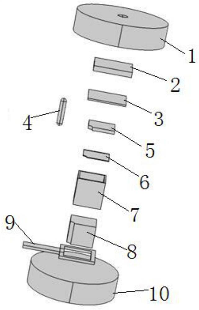
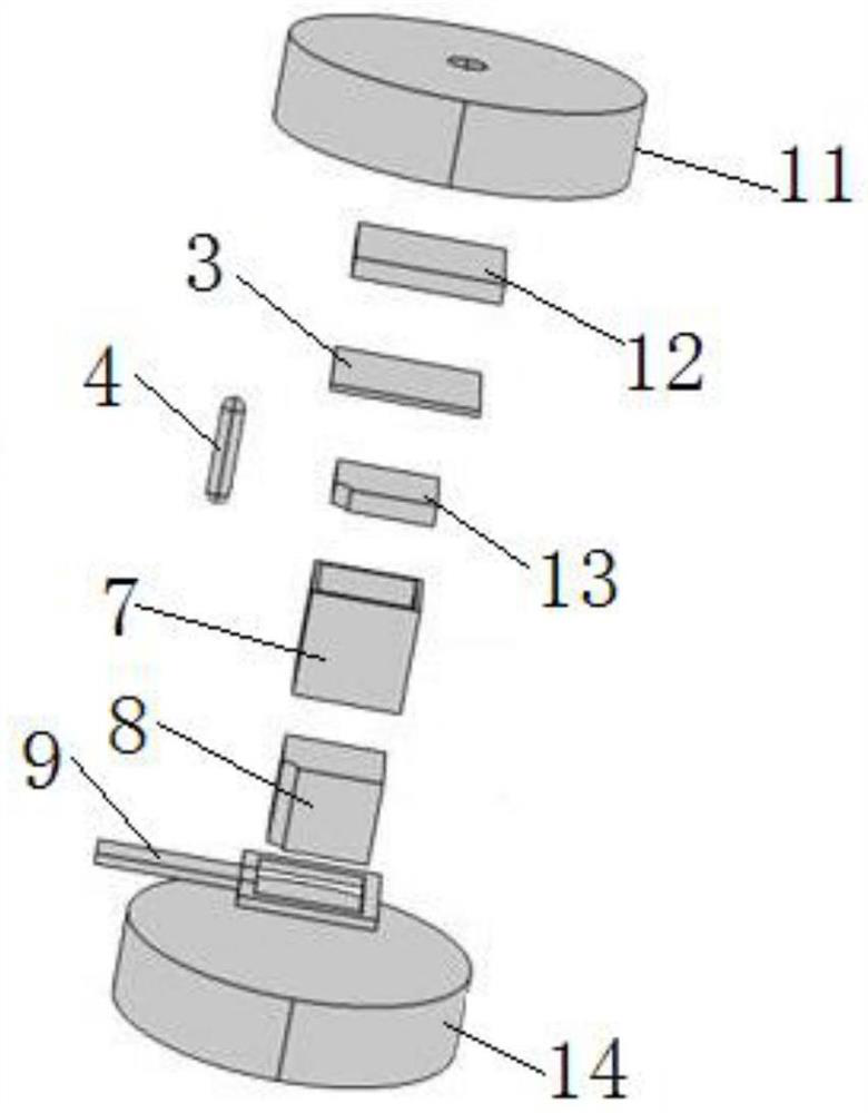
[0023] Embodiments of the present invention are described below through specific examples, and those skilled in the art can easily understand other advantages and effects of the present invention from the content disclosed in this specification. The present invention can also be implemented or applied through other different specific implementation modes, and various modifications or changes can be made to the details in this specification based on different viewpoints and applications without departing from the spirit of the present invention. It should be noted that the diagrams provided in the following embodiments are only schematically illustrating the basic concept of the present invention, and the following embodiments and the features in the embodiments can be combined with each other in the case of no conflict.

[0024] Wherein, the accompanying drawings are for illustrative purposes only, and represent only schematic diagrams, rather than physical drawings, and should...


PUM


Abstract

The invention relates to a crimping type IGBT power module based on gradient function composite material packaging, an IGBT sub-module between a collector metal layer and an emitter metal layer comprises a collector gradient function composite material layer, an IGBT power chip, an emitter gradient function composite material layer, a copper pedestal and a grid PCB which are successively crimped from top to bottom, a packaging shell support is sleeved outside the crimped IGBT sub-module, and gate spring ejector pins are placed in gaps of the crimped emitter gradient function composite material layer and the copper pedestal. The thermal expansion coefficients of the collector gradient function composite material layer, a collector metal layer, the collector surface of the IGBT power chip, the emitter gradient function composite material layer, the emitter surface of the IGBT power chip and the copper pedestal are matched. The problems that in an existing crimping type IGBT power module, thermal expansion coefficients between the IGBT power chip and a packaging material assembly are not matched, so that the electric heating contact performance of an assembly interface is reduced, the heat dissipation efficiency is reduced, and the service life of a device is shortened are solved.

Description

technical field [0001] The invention belongs to the field of power semiconductor devices and relates to a crimping type IGBT power module packaged based on gradient functional composite materials. Background technique [0002] Compared with IGBT power modules with welded package structure, IGBT power modules with crimped package structure have the advantages of high power density, double-sided heat dissipation, low on-state loss, strong impact resistance, large flow capacity, failure short circuit and easy series connection, etc. It is suitable for the application conditions of high-voltage and large-capacity power equipment such as MMC converter valves in flexible direct current transmission systems. A small number of crimp-type IGBT power modules can meet the voltage level and capacity requirements of MMC converter valves, effectively reducing the The integrated manufacturing and operation and maintenance of large-capacity power equipment are difficult, and have broad mark...

Claims


Application Information

Patent Timeline
IPC IPC(8): H01L23/367H01L23/373H01L23/10H01L29/739H01L25/07
CPCH01L23/367H01L23/373H01L23/10H01L29/7393H01L25/072
Inventor 张豫川钟星立龙海洋
Owner CISDI ENG CO LTD
Why Eureka
Try Eureka