Ultrasonic vibration device and design method

A technology of ultrasonic vibration and design method, applied in the direction of fluid using vibration, design optimization/simulation, milling machine equipment, etc., can solve the problems of low shape and position accuracy, many burrs, poor surface quality, etc.

Pending Publication Date: 2021-06-11
安徽天航机电有限公司
View PDF0 Cites 2 Cited by
  • Summary
  • Abstract
  • Description
  • Claims
  • Application Information

AI Technical Summary

Problems solved by technology

[0004] Therefore, this application proposes to design an ultrasonic vibration-assisted drilling and milling device to solve the problems of poor surface quality,

Method used


Image

  • Ultrasonic vibration device and design method
  • Ultrasonic vibration device and design method
  • Ultrasonic vibration device and design method

Examples


Embodiment Construction

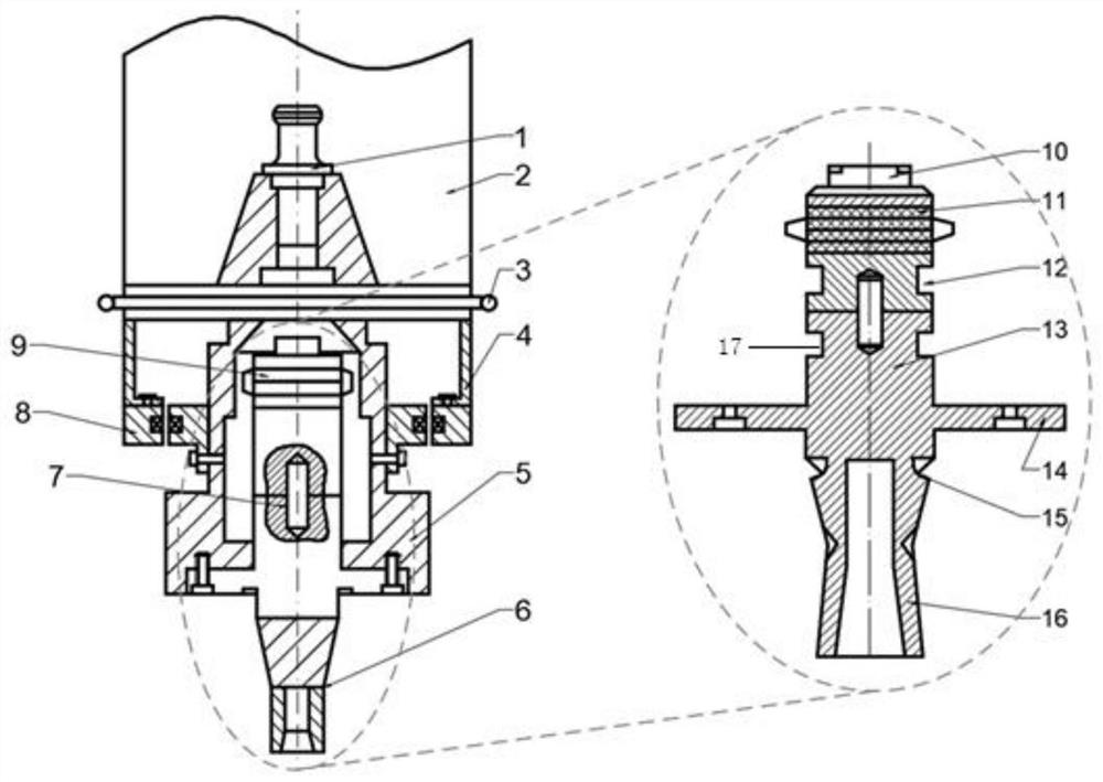
[0051] This application will design an ultrasonic vibration auxiliary processing device with a frequency of 20KHz, multi-tool clamping, large amplitude and wide adjustable range, and stable vibration performance. Such as figure 1 As shown, it includes an ultrasonic vibration auxiliary processing device spindle 1, an ultrasonic power supply, an ultrasonic wireless power transmission system 8, a longitudinal ultrasonic vibration transducer 9, an ultrasonic horn 6 and other connecting devices. The power output end of the machine tool spindle 2 is set vertically downward, the machine tool spindle 2, the installation cylinder, the sleeve, the horn and the cutting tool have the same rotation center line, the lower end of the machine tool spindle is coaxially connected with the upper end of the installation cylinder 4, and the lower part of the installation cylinder extends Out of the main shaft housing, the upper part of the sleeve is placed on the lower part of the main shaft housi...


PUM

PropertyMeasurementUnit
Thicknessaaaaaaaaaa

Abstract

The invention discloses an ultrasonic vibration device and a design method. The problems of large cutting force, high cutting temperature, low machining precision and the like of difficult-to-machine materials such as composite materials, hard alloy and the like during machining are solved. Anultrasonic vibration auxiliary drilling and milling device is designed, a rear cover plate, piezoelectric ceramics and a front cover plate of a piezoelectric transducer are respectively made of 45 steel, PZT-8 and duralumin materials, so that good piezoelectric conversion characteristics and axial displacement output are achieved; and an ultrasonic amplitude-change pole is designed into a conical transition type composite amplitude-change pole, and the tail end of the amplitude-change pole is designed into a groove type, so that the large amplification factor is achieved, and the resonant frequency can be corrected by adjusting counterweight liquid in the groove.

Description

technical field [0001] This application relates to ultrasonic vibration assisted processing technology, combined with ultrasonic vibration technology, transforming traditional continuous processing into periodic pulse processing. Background technique [0002] In recent years, aerospace and other fields have developed rapidly, and materials such as composite materials, hard alloys, and titanium alloys have become more and more widely used. Due to the characteristics of such materials such as high hardness, high strength, and low thermal conductivity, the use of traditional machining will cause problems such as excessive cutting force and high cutting heat in the cutting area, resulting in machine tool vibration, tool wear, and chip adhesion. Make the surface quality and shape and position tolerance difficult to meet the requirements. In order to further improve the machining quality of key parts, it is urgent to propose a new machining method. [0003] Ultrasonic vibration ...

Claims


Application Information

Patent Timeline
IPC IPC(8): B23B19/02B23B35/00B23C3/00B06B1/06G06F30/17G06F30/23
CPCB23Q1/70B23B35/00B23C3/00B06B1/06G06F30/17G06F30/23B23B2270/10B23C2270/10
Inventor 佟政阳陈卫林丁庆昌陶悦
Owner 安徽天航机电有限公司
Why Eureka
Try Eureka