

Biochar production and processing equipment
A processing equipment and technology of biochar, applied in the petroleum industry, grain processing, fixed carbonization furnace, etc., can solve the problems of uneven carbonization degree of biochar, low energy utilization rate of combustion furnace, and uneven structure, etc., to achieve Improve carbonization effect, improve carbonization efficiency, and achieve consistent carbonization degree
- Summary
- Abstract
- Description
- Claims
- Application Information
AI Technical Summary
Problems solved by technology
Method used
Image

Examples
Embodiment Construction
[0019] The technical solution in the present invention will be clearly and completely described below in conjunction with the drawings in the embodiments of the present invention. Obviously, the described embodiments are only part of the embodiments of the present invention, not all of them.
[0020] In the description of the present invention, it should be noted that unless otherwise specified and limited, the terms "connected" and "connected" should be understood in a broad sense, for example, it can be a fixed connection, a detachable connection, or an integral Ground connection; it can be mechanical connection or electrical connection; it can be direct connection or indirect connection through an intermediary. Those of ordinary skill in the art can understand the specific meanings of the above terms in the present invention in specific situations.
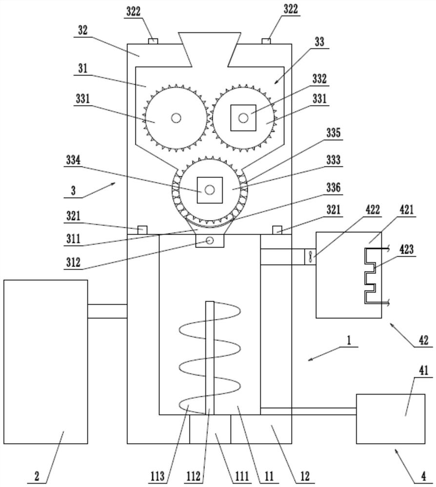
[0021] refer to figure 1 As shown, a preferred embodiment of the present invention, a biochar production and processing equi...
PUM
 Abstract
Description
Claims
Application Information