BOG comprehensive utilization system for LNG receiving station

A receiving station and entrance technology, which is applied in the pipeline system, liquid bottling, packaging items, etc., can solve the problems of resource waste and adverse environmental impact, reduce energy loss and waste, realize cascade utilization, and improve energy utilization. Effect

Pending Publication Date: 2021-06-15
ZHEJIANG ZHENENG TECHN RES INST
View PDF0 Cites 7 Cited by
  • Summary
  • Abstract
  • Description
  • Claims
  • Application Information

AI Technical Summary

Problems solved by technology

[0004] In summary, the conventional BOG treatment process has the waste of resources, and the CO produced by BOG combustion 2 Adverse effects on the environment etc.

Method used


Image

  • BOG comprehensive utilization system for LNG receiving station
  • BOG comprehensive utilization system for LNG receiving station
  • BOG comprehensive utilization system for LNG receiving station

Examples


Embodiment 1

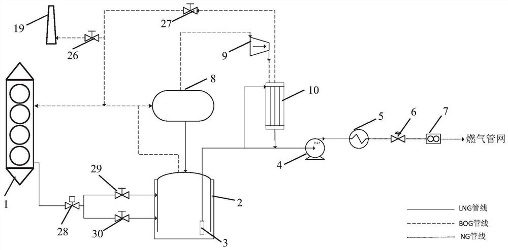
[0031] 1. An LNG receiving station BOG comprehensive utilization system, including: LNG transport boat 1, LNG tank 2, potential pump 3, high pressure pump 4, vaporizer 5, voltage regulator A6, metering device A7, buffer can 8, BOG compressor 9, re-condenser 10, seawater pump 11, heat exchanger A12, heat exchanger B13, power generating device 16, lithium bromide 17, waste heat boiler 18, torch 19 and multiple valves;

[0032] LNG transport ship 1 export pipe connection LNG storage tank 2 inlet, LNG storage tank 2 outlet connection buffer can 8 inlet, buffer can 8 outlet connection BOG compressor 9 inlet, BOG compressor 9 outlet connection reconductor 10 inlet; LNG storage The can 2 has a potential pump 3, the outlet airway of the sub-potential pump 3 is connected to the re-condenser 10; the re-condenser 10 is applied to the high pressure pump 4 inlet, the high pressure pump 4 outlet connection vaporizer 5 inlet, the vaporizer 5 outlet connection regulation A6 entrance, voltage regu...

Embodiment 2

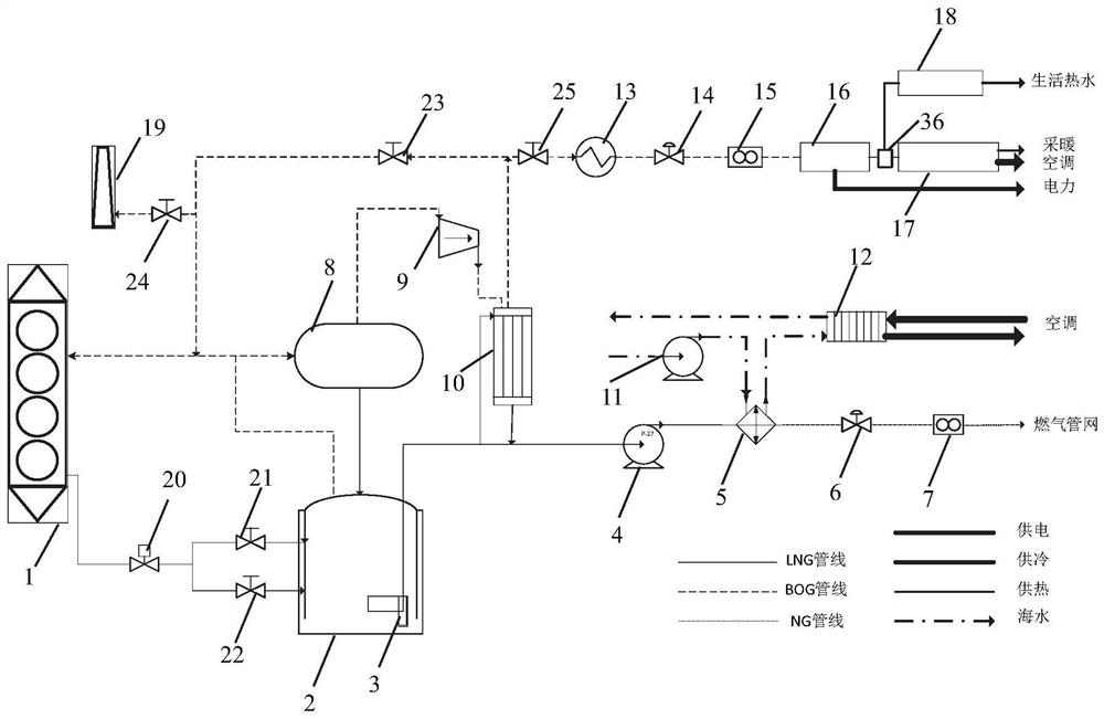
[0036] Such as figure 2 As shown, a method of working use of the LNG receiving station BOG comprehensive utilization system is:

[0037] LNG unloading operating conditions, when the discharge from the LNG transport ship 1 enters the LNG storage tank 2, the flash generates a quantity of BOG, so that the pressure of the LNG storage tank 2 increases, and the partial BOG will return to the LNG through the gas phase return pipe. On the boat, part -150 ° C, 115 kPa of BOG enters the buffer can 8, and the re-condenser 10 is entered after pressurizing to 1800 kPa via the BOG compressor 9. -161.00 ° C, 115 kPa LNG was pressurized to 550 kPa to 550 kPa into the recondensator 10, and the ultra-cold state liquefied liquefied, liquefied LNG and the LNG flowing out of the sub-liquid pump 3 were added. Pressure to 6500 kPa, the temperature increases to -135 ° C to enter the ORV vaporizer 5, and the LNG enters the urban gas pipe network after the modulator A6 and the metrological device A7 are tu...


PUM


Abstract

The invention relates to a BOG comprehensive utilization system for an LNG receiving station. The BOG comprehensive utilization system for the LNG receiving station comprises an LNG transport ship, an LNG storage tank, an immersed pump, a high-pressure pump, a vaporizer, a pressure regulator A, a metering device A, a buffering tank, a BOG compressor, a recondenser, a sea water pump, a heat exchanger A, a heat exchanger B, a power generation device, a lithium bromide unit, a waste heat boiler, a torch and a plurality of valves. The BOG comprehensive utilization system for the LNG receiving station has the following beneficial effects: a gas internal-combustion engine is used for combusting BOG for power generation, and BOG originally discharged through combustion is reused, so that the technical effects of energy conservation and emission reduction are realized; a heat exchange pipeline is arranged, and a free cold source is provided for an air conditioner through seawater; while the need of a vaporization process is met, gradient utilization of energy is realized through cold energy recovery, and energy conservation and emission reduction are achieved; and different energy consumption requirements of the LNG receiving station can be met, waste can be turned into wealth, energy loss and waste are reduced, the energy utilization rate is increased, the gradient utilization of energy is realized, and a good good economic value is achieved.

Description

Technical field [0001] In particular, the present invention belongs to the technical field of evaporation gas in liquefied natural gas, and more particularly to an LNG (liquefied natural gas) receiving station BOG (evaporation gas) comprehensive utilization system. Background technique [0002] At present, there are two main types of operating conditions in China's large LNG receiving station. First, unload ship operating conditions, one is the external operational operating conditions. When the unloading operating conditions, the discharge enters the LNG (liquefied natural gas) storage tank, and a certain amount of BOG (evaporation gas) occurs, so that the pressure of the LNG tank is raised, and the portion of the BOG will return to the pipe through the gas phase. On the LNG board, the amount of flash generation and returning to the ship mutually cancel each other, the total amount of system BOG may increase, the key depends on the integration of multiple factors such as unloadi...

Claims


Application Information

Patent Timeline
Patent Type & Authority Applications(China)
IPC IPC(8): F17C9/04F17C6/00F17C13/00F17C13/02F17C13/04F17D1/08F17D3/01F17D3/18
CPCF17C6/00F17C9/04F17C13/00F17C13/02F17C13/04F17C2225/0161F17C2227/0128F17C2227/0388F17C2227/04F17C2260/044F17C2260/046F17C2265/03F17C2265/07F17D1/082F17D3/01F17D3/18
Inventor 张曦董益华林俊光陈思罗海华俞李斌赵申轶叶飞宇徐明阳蒋月红马聪
Owner ZHEJIANG ZHENENG TECHN RES INST
Why Eureka
Try Eureka