
Friction welding method with interlayer material added

A friction welding and intermediate layer technology, applied in welding equipment, non-electric welding equipment, metal processing equipment, etc., can solve the problems of low connection strength, affecting joint performance, poor plasticity, etc., and achieve the effect of easier softening

Active Publication Date: 2021-06-18
AVIC BEIJING AERONAUTICAL MFG TECH RES INST
View PDF7 Cites 0 Cited by
  • Summary
  • Abstract
  • Description
  • Claims
  • Application Information

AI Technical Summary

Problems solved by technology

[0002] Because TiAl and powdered superalloys still retain excellent comprehensive mechanical properties in high-temperature environments, they have gradually become excellent candidate high-temperature structural materials in the fields of modern aviation, aerospace, weapons and civil industries, but the weldability of such materials is poor. Difference
[0003] At present, the welding method of TiAl material is mainly brazing technology. TiAl brazing technology mainly realizes the connection by adding Ti-based or Ni-based solder with high wettability, but the method of brazing is used to effectively control the microstructure and interface of the brazed joint. The structure is difficult, the connection strength is low, and the stability is poor
The main problem of directly adopting linear and inertial friction welding technology for welding is that the strength of TiAl material is still high at high temperature, and its plasticity is poor. During the friction process, the friction type on the interface is mainly dry friction, and plastic deformation is not easy to occur. Insufficient heat input, the interface temperature is difficult to quickly reach the temperature required to form the joint, so it is difficult to obtain a reliable welded joint
[0004] A kind of composite welding method of dissimilar materials has been proposed in the related art. In this method, a heater device is added to the inertial friction welding equipment, and an intermediate transition layer with better mutual solubility is added between the two workpieces to be welded. First, the intermediate transition layer and the rotating The workpieces to be welded are non-vacuum, atmospheric pressure diffusion welding, followed by rotary friction welding to obtain welded joints with good welding quality. However, the welding section of this method is limited, and only cylindrical symmetrical structures can be welded, and the first step of diffusion welding requires Heating the whole workpiece to be welded to a higher temperature and holding it for a long time will inevitably have a great impact on the microstructure of the base metal of the workpiece to be welded, thereby affecting the performance of the joint. At the same time, there are two or more joints formed after welding. Welding interface, joint strength will be adversely affected

Method used


Image

  • Friction welding method with interlayer material added
  • Friction welding method with interlayer material added
  • Friction welding method with interlayer material added

Examples


Embodiment 1

[0064] Embodiment 1: In this embodiment, the middle layer material is added on the end face of the workpiece to be welded by laser additive manufacturing.

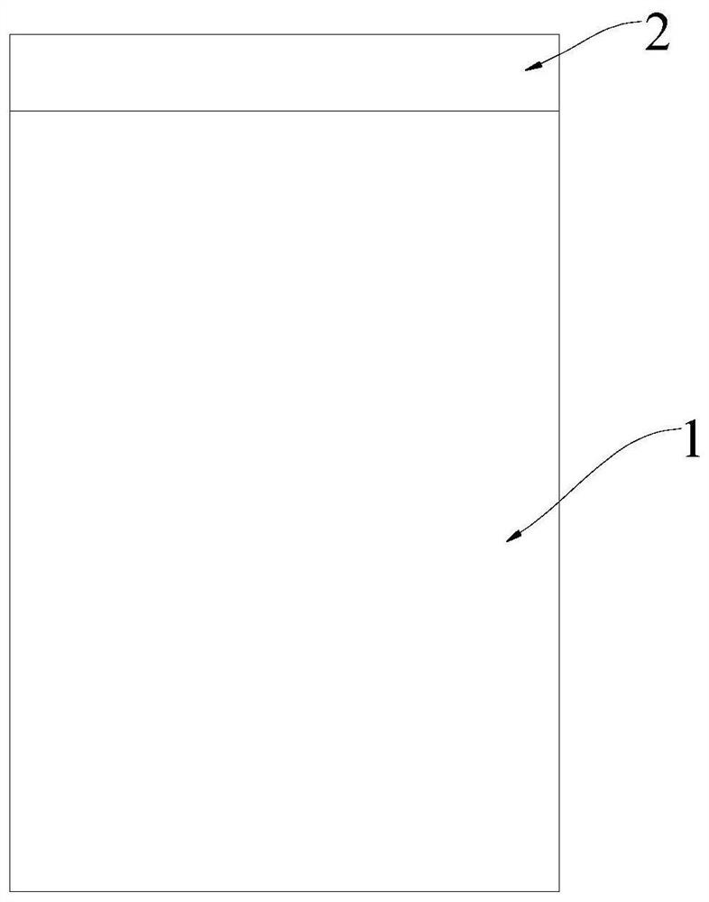
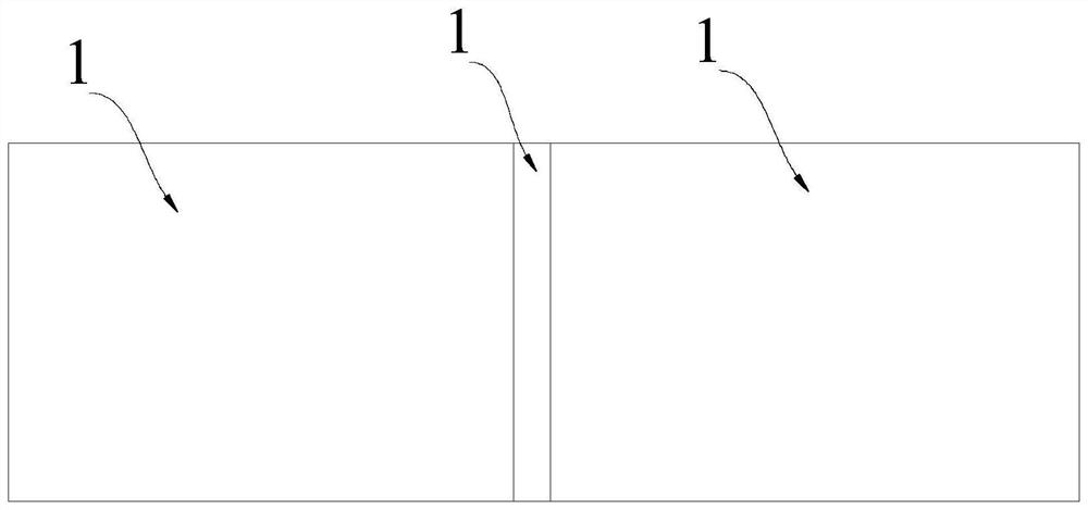
[0065] In the friction welding method of the embodiment of the present invention, the size of the workpiece 1 to be welded is 12.5mm×25mm×50mm, and 12.5mm×25mm is used as the welding end of the workpiece 1 to be welded.

[0066] Step 1: Perform sandblasting pretreatment on the surfaces of the two workpieces 1 to be welded.

[0067] Step 2: Wipe the surfaces of the two workpieces 1 to be welded with alcohol to remove impurities on the surfaces of the workpieces 1 to be welded.

[0068] Step 3: The welding ends of the two workpieces 1 to be welded in step 2 are stacked with the original intermediate layer 2 by the method of laser additive manufacturing, and the material of the laser additive is Ti 2 AlNb or titanium alloy powder. The thickness H of the raw intermediate layer 2 = 8 mm.

[0069] Step 4: Machining the origin...

Embodiment 2

[0073] Embodiment 2: In this embodiment, the intermediate layer material added on the end surface of the workpiece to be welded is mechanically fixed.

[0074] In the friction welding method of the embodiment of the present invention, the size of the workpiece 1 to be welded is 75mm×20mm×130mm, and 75mm×20mm is used as the welding end of the workpiece 1 to be welded.

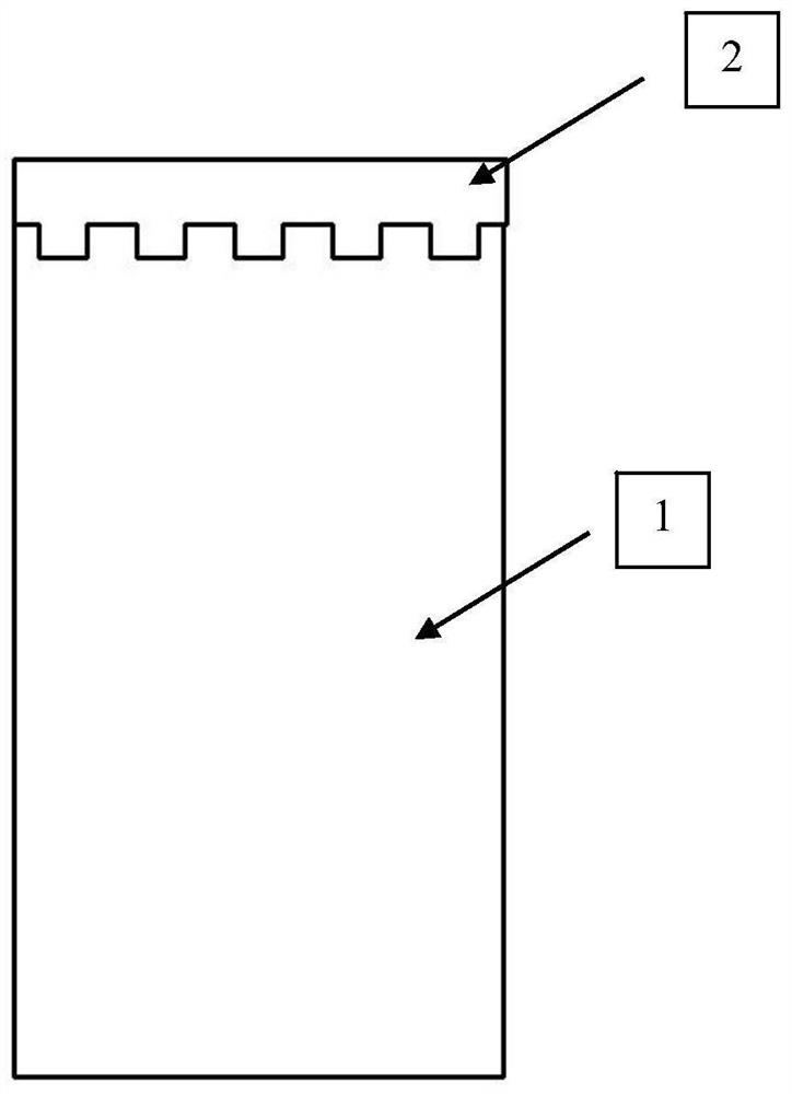
[0075] Step 1: Machining grooves on one end of the two workpieces 1 to be welded, correspondingly setting a boss on the workpiece 2 corresponding to the workpiece 1 to be welded to ensure that the workpiece 1 to be welded and the original intermediate layer can form a good fixation . Wherein the height of the boss and the depth of the groove are both no more than 5mm.

[0076] Step 2: install the workpiece 1 to be welded on the vibrating fixture and the upsetting fixture on the linear friction welding machine respectively, and install the original intermediate layer 2 and the workpiece 1 to be welded together. ...


PUM

PropertyMeasurementUnit
Thicknessaaaaaaaaaa

Abstract

The invention relates to a friction welding method with an interlayer material added. The method is used for realizing the welding of brittle metal or dissimilar metal materials, and comprises the following steps of: pretreating two to-be-welded workpieces; adding an original interlayer to at least one welding end of the two to-be-welded workpieces; installing the to-be-welded workpiece provided with the original interlayer in the two to-be-welded workpieces on a vibrating or rotating clamp, and installing the other to-be-welded workpiece in the two to-be-welded workpieces on an upsetting clamp; wiping the surfaces of the two to-be-welded workpieces with an organic solvent or a cleaning agent to remove impurities on the surfaces of the to-be-welded workpieces; and according to the materials of the two to-be-welded workpieces, adopting the corresponding friction welding parameters for welding. According to the friction welding method, the to-be-welded workpieces can be preheated in the friction welding process, so that the to-be-welded workpieces are more prone to plastic deformation, and therefore reliable connection of fragile and dissimilar metal materials is achieved.

Description

technical field [0001] The invention relates to the field of welding technology, in particular to a friction welding method, which is suitable for effective connection of brittle or dissimilar materials (such as TiAl, steel, superalloy, etc.). Background technique [0002] Because TiAl and powdered superalloys still retain excellent comprehensive mechanical properties in high-temperature environments, they have gradually become excellent candidate high-temperature structural materials in the fields of modern aviation, aerospace, weapons and civil industries, but the weldability of such materials is poor. Difference. [0003] At present, the welding method of TiAl material is mainly brazing technology. TiAl brazing technology mainly realizes the connection by adding Ti-based or Ni-based solder with high wettability, but the method of brazing is used to effectively control the microstructure and interface of the brazed joint. The structure is difficult, the connection strengt...

Claims


Application Information

Patent Timeline
IPC IPC(8): B23K20/12
CPCB23K20/12
Inventor 常川川金俊龙李菊陶军
Owner AVIC BEIJING AERONAUTICAL MFG TECH RES INST
Learn More