


Quick Research
Generate reliable direction feasibility study reports for your R&D in just a few steps.

Technical Q&A
Discover and master advanced knowledge NOW. Basics, ideas, possibilities, all at once.

Find Solutions
As an expert in R&D theories, this can generate solutions to your technical problems instantly.

Evaluate Feasibility
Analyze your overall solution with one click, know your potential R&D risks in advance.

Monitor Landscape
Get weekly tech updates, stay abreast of the latest tech innovations and key insights.
Cathode flowing electrode liquid, flowing electrode capacitive deionization device and application of flowing electrode capacitive deionization device
A technology of capacitive deionization and flowing electrodes, which is applied in the field of capacitive deionization devices of flowing electrodes and cathode flowing electrode solution, can solve the problem of difficult to ensure stable, long-term and high-efficiency operation of the reactor, low charge transfer efficiency of collectors and flowing electrodes, Improve the regeneration and stable cycle performance, cost-effective, and improve the removal efficiency due to problems such as the increase of the viscosity of the flow electrode
- Summary
- Abstract
- Description
- Claims
- Application Information
AI Technical Summary
Problems solved by technology
Method used
Image

Examples
Embodiment 1
[0034] A cathodic flowing electrode solution, including electrolyte, conductive agent, redox active material and solvent.
[0035] In this embodiment, the concentration of the redox active substance in the cathode flowing electrode solution is 3 mM, and the redox active substance is KI 3 .
[0036] In this embodiment, the concentration of the electrolyte in the cathode flowing electrode solution is 1000 mg / L, and the electrolyte is KCl.
[0037] In this embodiment, the concentration of the conductive agent in the cathode flowing electrode solution is 60 g / L, and the conductive agent is activated carbon and carbon black, and the mass ratio of the two is 5:1.
[0038] In this embodiment, the solvent is water.
[0039] A method for preparing the cathodic flowing electrode solution in the above-mentioned embodiment of the present invention, comprising the following steps:
[0040] (1) Weigh I 2 Dissolve KI in 100mL KCl solution with a concentration of 1000mg / L, mix well, and r...
Embodiment 2
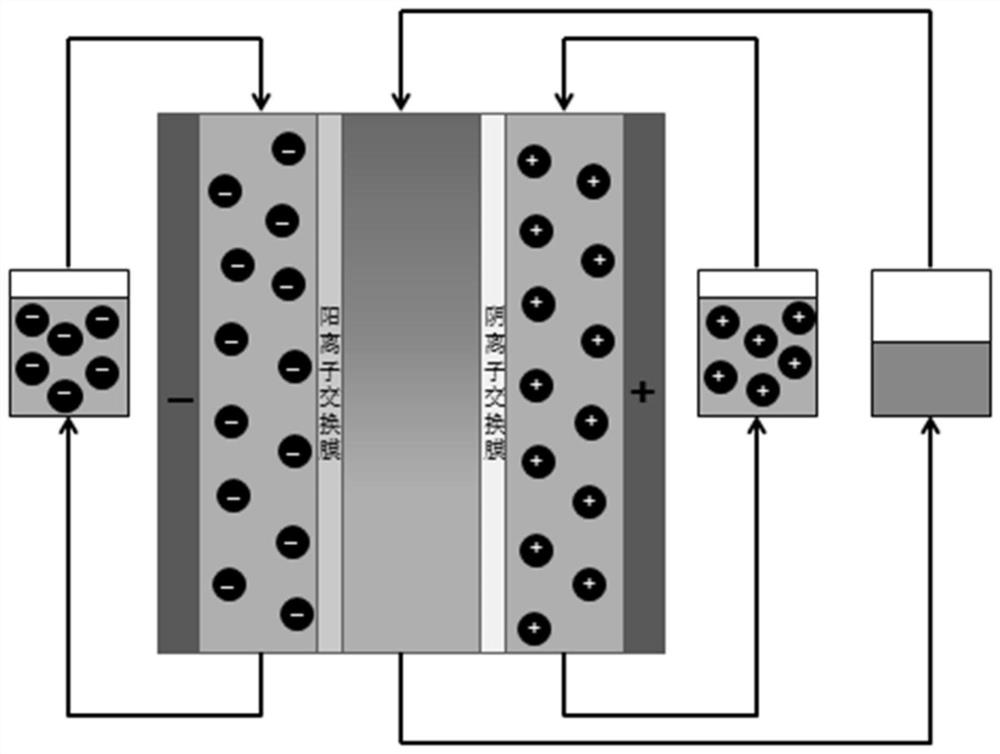
[0044] A flow electrode capacitive deionization device, its structure schematic diagram is as follows figure 1 As shown, it includes an anode flow electrode chamber, a water inlet chamber and a cathode flow electrode chamber, wherein the cathode flow electrode chamber contains the cathode flow electrode solution prepared in Example 1 with different concentrations of redox active substances.
[0045] In this embodiment, an anion exchange membrane is arranged between the anode flow electrode chamber and the water inlet chamber, and a cation exchange membrane is arranged between the cathode flow electrode chamber and the water inlet chamber; A current collector, wherein the current collector is a graphite plate with a serpentine flow channel.
[0046] In this embodiment, the anode flow electrode chamber also contains an anode flow electrode solution, wherein the anode flow electrode solution includes electrolyte, conductive agent and solvent; specifically: the concentration of th...
Embodiment 3
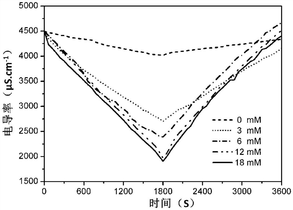
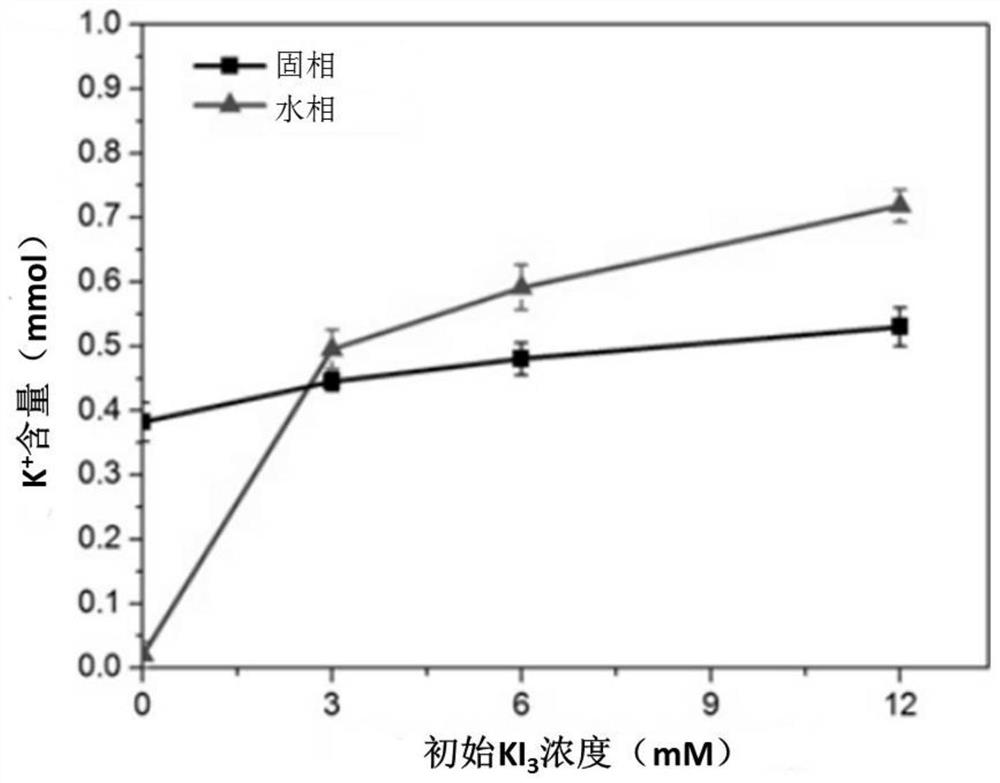
[0050] An application of a flowing electrode capacitive deionization device in water body purification, specifically for utilizing the flowing electrode capacitive deionization device (B0, B1, B2, B3) in embodiment 2 to process potassium chloride solution, comprising the following steps:
[0051] At a flow rate of 25mL / min, 50mL of KCl solution with a concentration of 3000mg / L was pumped into the water inlet chamber through the water inlet pipe and circulated in the water inlet chamber. At the same time, the flow rate of the cathode flow electrode solution in the cathode flow electrode chamber was controlled as 50mL / min, and control the flow rate of the anode flow electrode solution in the anode flow electrode chamber to be 50mL / min, after the conductivity is stable, power on, and control the voltage between the anode flow electrode chamber and the cathode flow electrode chamber to be 1.2V, namely Apply a constant voltage of 1.2V to the mobile electrode capacitive deionization ...
PUM
 Abstract
Description
Claims
Application Information
 - R&D Engineer
- R&D Manager
- IP Professional
- Industry Leading Data Capabilities
- Powerful AI technology
- Patent DNA Extraction
Browse by: Latest US Patents, China's latest patents, Technical Efficacy Thesaurus, Application Domain, Technology Topic, Popular Technical Reports.
© 2024 PatSnap. All rights reserved.Legal|Privacy policy|Modern Slavery Act Transparency Statement|Sitemap|About US| Contact US: help@patsnap.com