Suspended strip line ultra-wideband zero-point-adjustable band-pass filter

A band-pass filter and ultra-broadband technology, which is applied in waveguide devices, resonators, electrical components, etc., can solve the problems of difficult transmission zero points in structural forms, difficulty in introducing transmission zero points, poor filter response, etc., and achieve structural Compactness, size reduction, and low cost effect

Active Publication Date: 2021-06-18
10TH RES INST OF CETC
View PDF6 Cites 4 Cited by
  • Summary
  • Abstract
  • Description
  • Claims
  • Application Information

AI Technical Summary

Problems solved by technology

Using cascaded high- and low-pass filters is equivalent to using two filters to realize the function of a band-pass filter, which is too bulky; microstrip multi-mode resonance technology is one of the mainstream technologies for realizing ultra-wideband filters, but due to It has only one resonator, and it is difficult to introduce a transmission zero point outside the passband in terms of structure; low-temperature co-fired ceramic technology and liquid crystal polymer technology are complex in processing and high in cost, and it is difficult to introduce a transmission zero point
After simulation, it is found that the filter response is not good, and the standing wave is relatively large

Method used


Image

  • Suspended strip line ultra-wideband zero-point-adjustable band-pass filter
  • Suspended strip line ultra-wideband zero-point-adjustable band-pass filter
  • Suspended strip line ultra-wideband zero-point-adjustable band-pass filter

Examples


Embodiment Construction

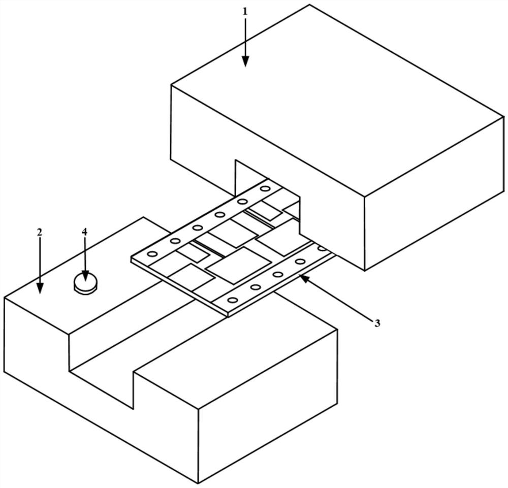
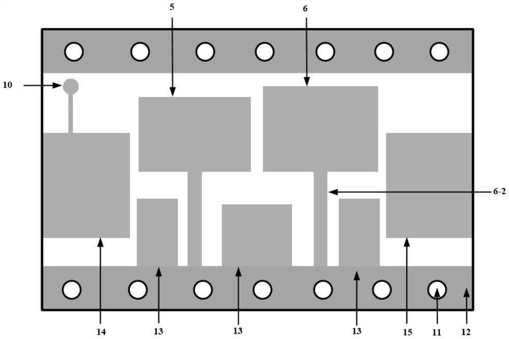
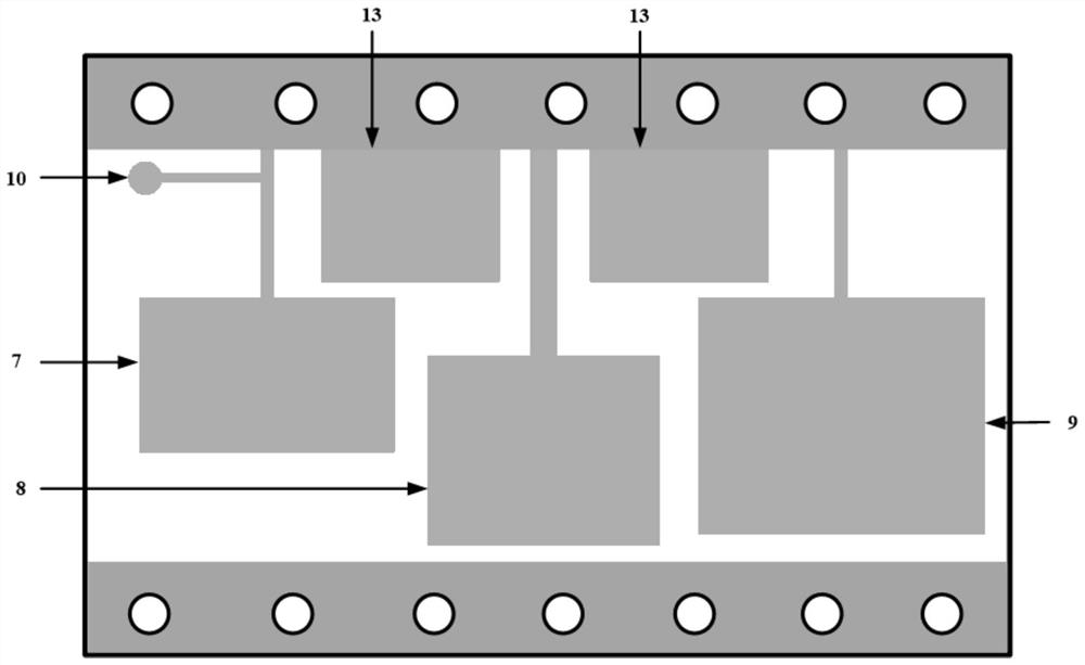
[0023] See Figure 1 - Figure 3 . In the preferred embodiment described below, a suspension strip ultra-wideband adjustable zero-point bandpass filter, including a metal, a lower chamber, a metal chamber, a metal, or a metal under a metal, a metal chamber On the dielectric substrate 3 and the medium substrate 3 between the bodies 2, a regions of the transmission line is employed as a transmission line of the transmission line, characterized in that the dielectric coupled via hole, a medium, a line array, a medium, a medium, and a medium. The front side distribution of the substrate 3 is provided between at least five resonators and a bilateral metalized coupled via 10 between the two-row metallized coupled via holes, wherein the first resonator 5 and the second resonator 6 are fixed. The medium substrate 3 front, the third resonator 7, the fourth resonator 8, and the fifth resonator 9, is fixed to the back surface of the dielectric substrate 3, and each resonator is from the main r...


PUM


Abstract

A suspended strip line ultra-wideband zero-point-adjustable band-pass filter disclosed by the invention is small in area, high in integration level and excellent in standing wave performance. According to the technical scheme, at least two resonators and a double-layer metallization coupling via hole which are arranged between double rows of metallization coupling via holes are distributed on the front face and the back face of a dielectric substrate, and each resonator is jointly composed of a main resonator located on one side and a resonator loading capacitor located on the other side; the resonator loading capacitors of all the resonators are connected with the metal ground at the two sides of the dielectric substrate; and transmission lines at the two ends achieve connection of the upper layer and the lower layer through a metalized through hole, and the self-resonant frequency of each resonator can be adjusted by adjusting the size of the resonator loading capacitor on the back face of the dielectric substrate of the resonator. The size of the capacitance loading part is increased, so that the self-resonant frequency of the resonators shifts towards the low-end direction of the frequency, the capacitance loading size of the back surface of the resonators is reduced, the self-resonant frequency of the resonators shifts towards the high-end direction of the frequency.

Description

Technical field [0001] The present invention relates to a radio frequency microwave filter, in particular a band pass filter capable of being widely used in the front end of the RF communication system. Background technique [0002] Filters are one of the indispensable devices in wireless communication systems. With the development of new technologies in RF / microwave, the filter also develops high performance, miniaturization, high power capacity, light weight, and low cost direction. In the communication system, the signal will be subject to the interference of the external environment noise signal, and the harmonic effects generated within the system for non-linearity, which significantly reduces the communication quality of the communication system. In order to suppress the interference signals outside the system and the harmonic signal generated by nonlinearity, it is necessary to add a filter in the system to ensure that the useful signal can be passed in a smaller loss, a...

Claims


Application Information

Patent Timeline
Patent Type & Authority Applications(China)
IPC IPC(8): H01P1/20H01P7/00
CPCH01P1/20H01P7/00
Inventor 徐照旭钟鸣海蔡喆
Owner 10TH RES INST OF CETC
Why Eureka
Try Eureka