Electric automobile and power battery heating system and heating method thereof
A power battery and heating method technology, applied in the direction of electric vehicles, motor generator control, control systems, etc., can solve problems such as slowing down the pulse current generation speed, unexpected driving or shaking of the vehicle, and unstable three-phase current feedback , to achieve the effect of increasing heating speed, small fluctuation, and avoiding unexpected driving or shaking
- Summary
- Abstract
- Description
- Claims
- Application Information
AI Technical Summary
Problems solved by technology
Method used
Image

Examples
Embodiment Construction
[0039] The present invention will be described in detail below in conjunction with the accompanying drawings.
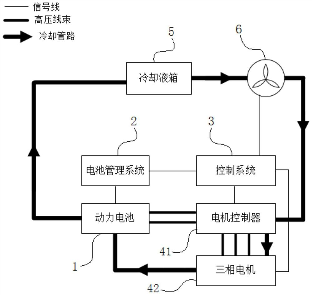
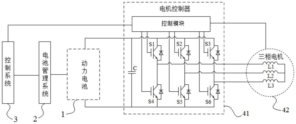
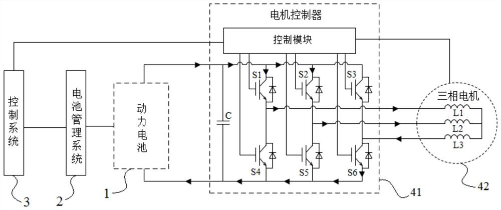
[0040] Such as Figure 1 to Figure 7 As shown, in the power battery heating method in this embodiment, the motor system used includes a motor controller 41 and a three-phase motor 42, the three-phase motor 42 is a Y-connected three-phase three-wire motor, and the motor controller 41 includes a control module , Three-phase bridge arm and bus capacitor C, the three-phase bridge arm is composed of U-phase bridge arm, V-phase bridge arm and W-phase bridge arm in parallel, bus capacitor C is connected with U-phase bridge arm, V-phase bridge arm, and W-phase bridge arm in parallel. The U-phase bridge arm is composed of the upper bridge arm power switch S1 and the lower bridge arm power switch S4. The V-phase bridge arm is composed of the upper bridge arm power switch S2 and the lower bridge arm power switch S5. The W-phase bridge arm is composed of the upper bridge arm po...
PUM
 Abstract
Description
Claims
Application Information