
Method for determining concentration of liquid

A technology of concentration and liquid, which is applied in the direction of vibration measurement in fluid, measurement of propagation velocity, detection of response signal, etc., and can solve problems such as change of measurement section and degradation of measurement accuracy

Pending Publication Date: 2021-06-22
ROBERT BOSCH GMBH
View PDF1 Cites 0 Cited by
  • Summary
  • Abstract
  • Description
  • Claims
  • Application Information

AI Technical Summary

Problems solved by technology

However, the post-installation process can lead to changes in the measurement path and thus degrade the measurement accuracy

Method used


Image

  • Method for determining concentration of liquid
  • Method for determining concentration of liquid
  • Method for determining concentration of liquid

Examples


Embodiment Construction

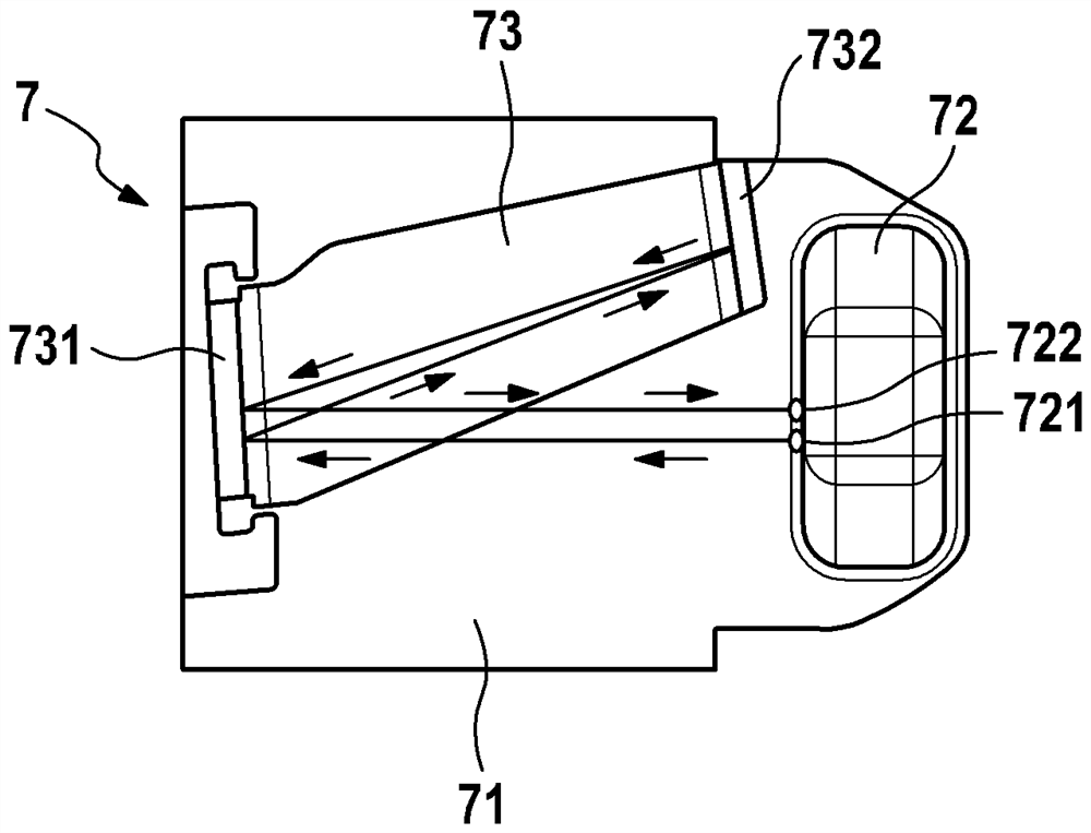
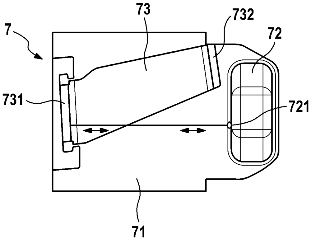
[0022] figure 1 Components of the SCR catalytic converter system 1 of the motor vehicle, not shown, are shown. The SCR catalytic converter system has a reductant tank 2 . A liquid 3 , which is HWL, is stored in the reducing agent tank 2 . The extraction module 4 is arranged at the bottom of the reducing agent tank 2 . The extraction module carries a delivery device 5 , by means of which liquid 3 can be drawn from the reducing agent tank 2 and transported by means of a line 6 to a metering valve of the SCR catalytic converter system 1 . To determine the concentration of the liquid 3 , a mass sensor 7 is arranged on the extraction module 4 , which is controlled by an electronic control unit 8 .

[0023] as in figure 2 As shown in , the mass sensor 7 has a base 71 , which in the exemplary embodiment consists of HDPE (High Density Polyethylene, high-density polyethylene). An ultrasonic transducer 72 is arranged on the base. Furthermore, in the present exemplary embodiment, ...


PUM


Abstract

A method for determining the concentration of a liquid is disclosed. The invention relates to a method for determining the concentration of a liquid (3), in which an ultrasonic transducer (72) and at least two ultrasonic reflecting surfaces (731, 732) are arranged on a carrier element (73) which is formed in a common one-piece manner, said at least two ultrasonic reflecting surfaces being at different distances from the ultrasonic transducer (72). The concentration is determined in a measurement operation from a first propagation time of the ultrasonic signal between the ultrasonic transducer (72) and the first ultrasonic reflecting surface (731) without having to reflect the ultrasonic signal at another ultrasonic reflecting surface (732). In a calibration operation, a first propagation time and a second propagation time (93, 94) of the ultrasound signal between the first ultrasound reflecting surface (731) and the at least one other ultrasound reflecting surface (732) are determined.

Description

technical field [0001] The invention relates to a method for determining the concentration of a liquid. The present invention also relates to a computer program implementing each step of the method and a machine-readable storage medium storing the computer program. Finally, the invention relates to an electronic control unit designed to carry out the method. Background technique [0002] In order to reduce the proportion of nitrogen oxides in the exhaust gas of an internal combustion engine, especially a diesel engine, it is known to arrange an SCR (Selective Catalytic Reduction, Selective Catalytic Reduction) catalytic converter converter in the exhaust gas line of said internal combustion engine, especially a diesel engine (Katalysator). The SCR catalytic converter reduces the nitrogen oxides contained in the exhaust gas in the presence of ammonia as nitrogen reducing agent. To provide ammonia, a reducing agent solution is injected into the exhaust gas line upstream of ...

Claims


Application Information

Patent Timeline
Patent Type & Authority Applications(China)
IPC IPC(8): G01N29/024F01N11/00F01N3/20
CPCF01N3/2066F01N11/00G01N29/024F01N2550/05F01N2560/12F01N2610/02F01N2900/1818G01N29/222G01N29/343G01N29/348G01N2291/0228G01N2291/0258G01N2291/02809G01N2291/045Y02T10/12G01H3/08G01H5/00G01N29/42
Inventor J·M·霍夫曼R·维因曼T·冈萨雷斯-巴奎特T·赫夫肯
Owner ROBERT BOSCH GMBH
Learn More