Application of Y6 in optical limiting
An optical limiting and strong laser technology, which is applied in the field of nonlinear materials, can solve problems such as damage, and achieve the effect of small size, large nonlinear absorption coefficient, and suitable for mass development and promotion.
- Summary
- Abstract
- Description
- Claims
- Application Information
AI Technical Summary
Problems solved by technology
Method used
Image
Examples
preparation example Construction
[0026] In one or some embodiments of the present disclosure, a method for preparing a Y6 thin film is provided, comprising the following steps: dissolving Y6 in chloroform to obtain a mixed solution, stirring the mixed solution, spin coating it on a substrate to form a film, and then drying, that is have to;
[0027] Preferably, the concentration of Y6 in the mixed solution is 9-10 mg / ml, preferably 9.12 mg / ml;
[0028] Preferably, the mixed solution is continuously stirred at a temperature of 30-50°C for 8-14 hours, more preferably at a temperature of 40°C for 12 hours;
[0029] Preferably, the drying temperature is 20-30°C, more preferably 25°C.
[0030] In one or some embodiments of the present disclosure, the application of the above-mentioned Y6 film or the product obtained by the above-mentioned Y6 film preparation method in the Z-scan optical path is provided.
[0031] In one or some embodiments of the present disclosure, an optical limiting device is provided, includ...
Embodiment 1
[0047] Embodiment 1 Preparation of Optical Limiting Device
[0048] This embodiment provides a method for preparing an optical limiting device, comprising the following steps:
[0049] Dissolve Y6 in chloroform, and the prepared Y6 concentration is about 9.12mg / ml. The mixed solution was continuously stirred at 40°C for 12 hours, and the cleaned quartz glass was transferred to a high-purity nitrogen-filled glove box, and the Y6 solution with a concentration of 9.12mg / ml was dropped on the substrate, and the rotation speed was 2500rpm Spin coating Form a film and then dry it at room temperature.
Embodiment 2
[0050] Embodiment 2 Optical limiting device performance test
[0051] 1. Measurement of two-photon absorption coefficient
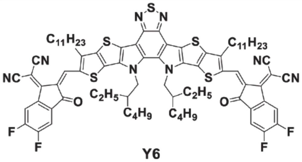
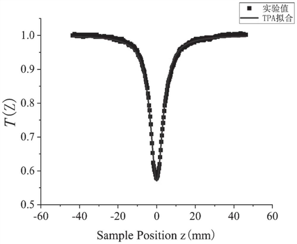
[0052]figure 1 It is the structural diagram of Y6 molecule. The two-photon absorption coefficient of Y6 film was measured by Z-scan technique. The laser used is spitfire PRO produced by Spectrophysics Corporation, and the laser output directly from the laser is 800nm linearly polarized light. The laser signal passing through the sample enters the silicon detector and then enters the connected lock-in amplifier, which is finally read directly by the computer. Use origin software to process the experimental data, such as figure 2 As shown, the black solid line is obtained by fitting the theoretical function, and all experiments were carried out at room temperature.
[0053] Z-scan technology is one of the important methods to measure the nonlinear absorption coefficient of materials. The principle is that the light intensity generated by the laser is...
PUM
| Property | Measurement | Unit |
|---|---|---|
| thickness | aaaaa | aaaaa |
| concentration | aaaaa | aaaaa |
| laser intensity | aaaaa | aaaaa |
Abstract
Description
Claims
Application Information
 - R&D
- Intellectual Property
- Life Sciences
- Materials
- Tech Scout
- Unparalleled Data Quality
- Higher Quality Content
- 60% Fewer Hallucinations
Browse by: Latest US Patents, China's latest patents, Technical Efficacy Thesaurus, Application Domain, Technology Topic, Popular Technical Reports.
© 2025 PatSnap. All rights reserved.Legal|Privacy policy|Modern Slavery Act Transparency Statement|Sitemap|About US| Contact US: help@patsnap.com


