
Active clamping push-pull buck-boost DC converter

A technology of DC converter and composite active clamp, which is applied in the direction of converting DC power input to DC power output, instruments, and adjusting electric variables, etc. It can solve the power circuit spurs, it is difficult to realize wide-range input and output changes, and the system is stable To avoid the adverse effects of sex and other problems, achieve the effect of low switch voltage stress, wide range of input voltage variation, and electrical isolation between output and input

Inactive Publication Date: 2021-06-29
QINGDAO UNIV
View PDF5 Cites 0 Cited by
  • Summary
  • Abstract
  • Description
  • Claims
  • Application Information

AI Technical Summary

Problems solved by technology

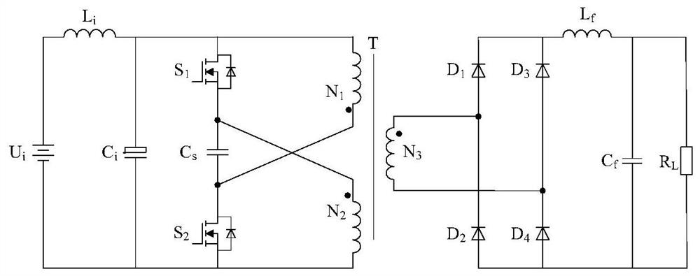
[0003] Traditional push-pull DC converters, such as figure 1 As shown, due to its simple structure, bidirectional magnetization of the transformer, high utilization rate of the magnetic core, no need for magnetic reset and isolation effect, it is widely used in these low-voltage input power conversion occasions, but most of the traditional push-pull DC converters As a Buck circuit, it is difficult to achieve a wide range of input and output changes. In addition, due to the effects of the transformer leakage inductance and the stray inductance of the power loop in the converter, when the power tube is turned off in the traditional push-pull converter, both ends of the power tube will be High voltage spikes are generated, which have adverse effects on the selection of power devices, system stability, etc.

Method used


Image

  • Active clamping push-pull buck-boost DC converter
  • Active clamping push-pull buck-boost DC converter
  • Active clamping push-pull buck-boost DC converter

Examples


Embodiment Construction

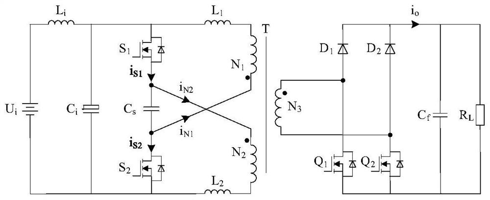
[0018] Bonded below figure 2 The first embodiment shown and Figure 4-6 The working principle of the active clamps proposed by the present invention is described as an example of working in the CRM mode. However, the invention is not limited to these examples. The present invention encompasses any alternative, modifications, equivalents, and programs made in the spirit and scope of the invention. Some specific details of the present invention will be detailed below. The description of these detail portions can also be fully understood in the art. At the same time, in order to more reflect the characteristics of the present invention, well-known methods, processes, processes, and elements are not described in detail.

[0019] figure 2 A structural diagram of the first embodiment of the active clamp push-pull elevator DC converter proposed by the present invention, figure 2 The positive direction of each current is also specified.

[0020] Figure 4 The first embodiment of the prese...


PUM


Abstract

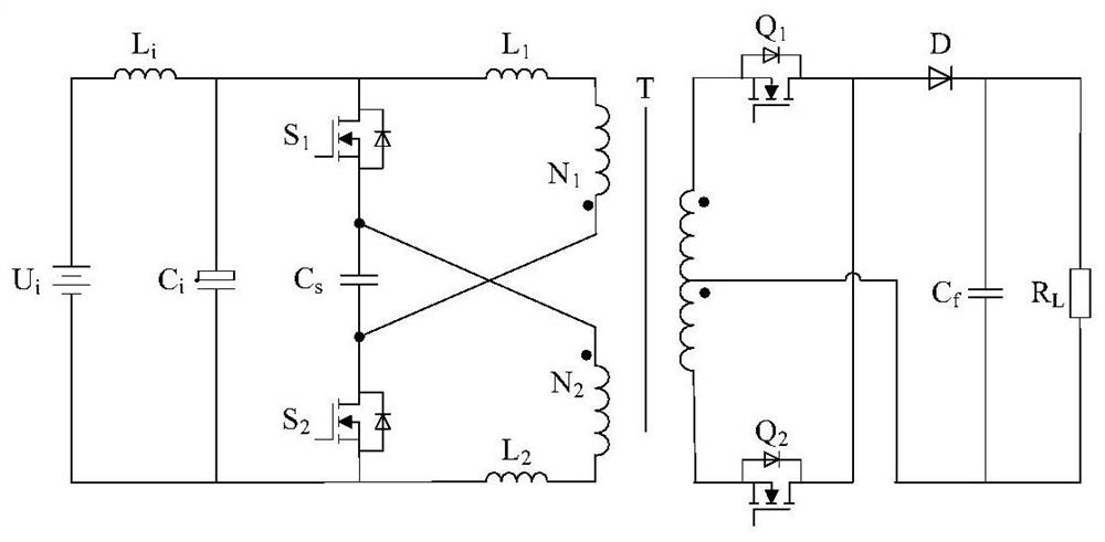
The invention discloses an active clamping push-pull buck-boost DC converter, and belongs to the power electronic conversion technology. The circuit structure is formed by cascading an input direct-current power supply, an input filter circuit, an active clamping push-pull circuit, a high-frequency transformer, a rectifying circuit, an output filter circuit and a direct-current load. According to the active clamping push-pull circuit, a clamping capacitor is connected in series between two switches of a traditional push-pull circuit, so that two active clamping circuits are formed, and inductance energy feedback is achieved. The rectifying circuit has a transformer short-circuit function, and is modified on the basis of a diode rectifying circuit, and a diode is replaced by a two-quadrant switch; and the converter controls storage and release of energy through simultaneous on-off of the primary side full-control switch and the secondary side full-control switch, can convert unstable direct current into stable and high-quality direct current, and has the advantages of being simple in circuit structure, isolated in input and output, low in power switch voltage stress, easy to control, high in reliability and the like. The converter is suitable for medium and small capacity low-voltage high-frequency isolation DC conversion occasions.

Description

Technical field: [0001] The active clamp push-pull lifting pressure DC converter proposed by the present invention belongs to power electronics. Background technique: [0002] With the development of power electronics, miniaturization, lightweight, high efficiency, high reliability and high stability of power electronic devices are the direction of the development of power electronic devices. Today, in a new energy power generating system in low-voltage input such as solar energy, fuel cells, the straight-line converter is an important part of it. [0003] Traditional push-pull DC converter, such as figure 1 As shown, since the structure is simple, the transformer is bidiren, the core utilization is high, and it is necessary to have a magnetic reset and have an isolation effect. It is widely applied to these low-voltage input electrical energy conversion applications, but the traditional push-pull DC converter For the BUCK circuit, it is difficult to implement the wide range of i...

Claims


Application Information

Patent Timeline
Patent Type & Authority Applications(China)
IPC IPC(8): H02M3/337
CPCH02M3/3376
Inventor 沈复颖江加辉马大壮赵嘉伟陈道炼
Owner QINGDAO UNIV
Learn More