Recycling method for generating carbon source by hydrolysis acidification of sludge of sewage plant

A technology for sludge hydrolysis and acidification, sewage treatment plant, applied in chemical instruments and methods, sludge treatment, biological sludge treatment, etc. Market Application Prospects, Optimizing Operating Costs, and the Effects of Optimizing Operating Conditions

Active Publication Date: 2021-07-02
联合环境技术(天津)有限公司
View PDF4 Cites 0 Cited by
  • Summary
  • Abstract
  • Description
  • Claims
  • Application Information

AI Technical Summary

Problems solved by technology

However, many domestic sewage plants face the problem of low carbon-to-nitrogen ratio of influent water, which leads to low efficiency of biological nitrogen and phosphorus removal. Therefore, many sewage plants often need to add carbon sources to achieve effective biological nitrogen and phosphorus removal. Commonly used carbon sources are glucose, sodium acetate, methanol or other synthetic carbon sources; this greatly increases the operating cost of the sewage plant

Method used


Image

  • Recycling method for generating carbon source by hydrolysis acidification of sludge of sewage plant
  • Recycling method for generating carbon source by hydrolysis acidification of sludge of sewage plant
  • Recycling method for generating carbon source by hydrolysis acidification of sludge of sewage plant

Examples


Embodiment 1

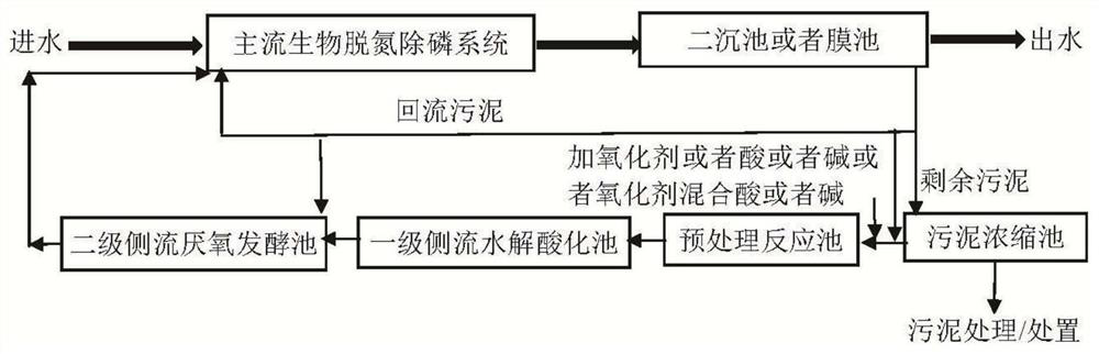
[0048] The concentration of the sludge in the secondary settling tank of the municipal sewage plant is 1.1%. Add 500 mg / L sodium hypochlorite to the sludge and mix it for 4 hours, then add it to the hydrolytic acidification tank equivalent to the side stream primary sludge hydrolysis acidification process section. The hydrolysis acidification tank keeps Run in continuous run CSTR mode with a 16 hour residence time at room temperature. The soluble COD SCOD of the sludge after pretreatment and primary side-stream hydrolysis and acidification increased from 38mg / L to 655mg / L. Then add 100 milliliters of sludge through side flow sludge pretreatment and primary side flow hydrolysis and acidification treatment in 1 liter equivalent to secondary side flow anaerobic fermentation tank, which is equivalent to 10% Q secondary sedimentation tank return sludge After the side stream pretreatment, add the first-stage side stream hydrolysis and acidification of the sludge, add 100 ml of secon...

Embodiment 2

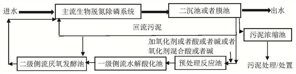
[0050] The concentration of the sludge in the secondary settling tank of the municipal sewage plant is 2.7%. Add 500mg / L sodium hypochlorite to the sludge and mix it for 4 hours before adding it to the hydrolytic acidification tank equivalent to the first-level side flow hydrolysis acidification process section of the side flow sludge. The hydrolytic acidification cell was maintained at room temperature for a 16-hour residence time and operated in a continuously operating CSTR mode. The soluble COD SCOD of the sludge after pretreatment and primary side-stream hydrolysis and acidification increased from 28mg / L to 839mg / L. Then add 100 milliliters of sludge through side flow sludge pretreatment and primary side flow hydrolysis and acidification treatment in 1 liter equivalent to secondary side flow anaerobic fermentation tank, which is equivalent to 10% Q secondary sedimentation tank return sludge Add 200 ml of anoxic pool sludge with a concentration of 0.5% after side stream pr...

Embodiment 3

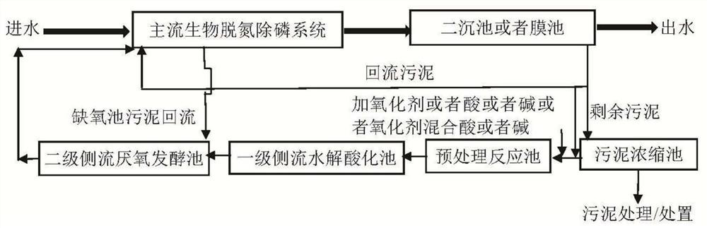
[0052] The concentration of the sludge in the membrane tank of the industrial sewage plant is 1.2%. Add 400mg / L30% sodium hydroxide to the sludge and mix it for 2 hours before adding it to the hydrolytic acidification tank which is equivalent to the side-stream sludge primary side-stream hydrolysis acidification process section. The primary hydrolytic acidification tank is maintained at 35°C for an 18-hour residence time and operated as a CSTR mode of continuous operation. After pretreatment and primary hydrolysis and acidification, the soluble COD SCOD of the sludge increased from 24mg / L to 582mg / L. Then add 120 milliliters of sludge through side flow pretreatment and first-level side flow hydrolysis acidification in 1 liter of equivalent side flow secondary side flow anaerobic fermentation tank, the membrane pool return sludge that is equivalent to 12% Q passes through Add 250 ml of anoxic pool sludge with a concentration of 0.55% after side stream pretreatment and side stre...


PUM


Abstract

The invention discloses a recycling method for generating a carbon source by hydrolysis acidification of sludge of a sewage plant, which comprises the following steps of: distributing part of sludge from return sludge of a biochemical sludge separation and interception system of a biochemical system to a side flow sludge pretreatment process section for pretreatment to realize primary wall breaking of sludge cells; and then allowing the sludge to enter a side-flow first-stage side-flow water hydrolysis acidification tank to realize hydrolysis acidification. The sludge subjected to hydrolysis acidification enters a second-stage side-flow anaerobic fermentation tank for side-flow for further fermentation. In the second-stage side-flow anaerobic fermentation tank, except for the sludge discharged into the first-stage side-flow water hydrolysis acidification treatment, a part of the sludge can be shunted from the return sludge of the biochemical sludge separation and interception system, or a part of the sludge is returned from an anoxic tank of a main flow biological nitrogen and phosphorus removal system to the second-stage side-flow anaerobic fermentation tank; and sludge treated by the second-stage side-flow anaerobic fermentation tank is discharged into a main flow biological nitrogen and phosphorus removal system to provide a carbon source. The method provided by the invention promotes the effect of biological nitrogen and phosphorus removal and realizes consumption reduction of carbon source and drug consumption.

Description

technical field [0001] The invention relates to the fields of sludge treatment and sewage treatment in sewage plants, in particular to a recycling method for generating carbon sources by hydrolysis and acidification of sludge in sewage plants. Background technique [0002] In order to achieve the stable compliance of effluent total nitrogen and total phosphorus in sewage plants, sewage plants need to effectively remove total nitrogen and total phosphorus through biological nitrogen and phosphorus removal systems. For biological nitrogen and phosphorus removal, it is generally recommended that the influent COD / TN should not be lower than 6 and the easily biochemical COD rCOD / TP should not be lower than 18. However, many domestic sewage plants face the problem of low carbon-to-nitrogen ratio of influent water, which leads to low efficiency of biological nitrogen and phosphorus removal. Therefore, many sewage plants often need to add carbon sources to achieve effective biologic...

Claims


Application Information

Patent Timeline
Patent Type & Authority Applications(China)
IPC IPC(8): C02F9/14C02F11/02C02F11/04C02F11/06C02F11/00C02F11/121
CPCC02F9/00C02F11/02C02F11/04C02F11/06C02F11/00C02F11/121C02F2209/06C02F3/302C02F3/308C02F2301/043C02F2305/06C02F3/1263C02F2209/04
Inventor 郭成洪林玉程李力阎怀国郭海军王津利史英君洪刚
Owner 联合环境技术(天津)有限公司
Why Eureka
Try Eureka