Welding method

A connecting wire and flux technology, which is applied in the direction of printed circuits connected with non-printed electrical components, printed circuits, printed circuit board additional/integrated components, etc., can solve the process of low efficiency, high requirements for operators, and peeling Waiting for questions

Active Publication Date: 2021-07-02
重庆炬特电子有限公司
View PDF4 Cites 0 Cited by
  • Summary
  • Abstract
  • Description
  • Claims
  • Application Information

AI Technical Summary

Problems solved by technology

[0003] It can be seen that there are some defects in the existing two welding methods. The defect of the first method is that there are many peeling procedures, which leads to low overall efficiency; as for the second method, it

Method used


Image

  • Welding method
  • Welding method
  • Welding method

Examples


Embodiment 1

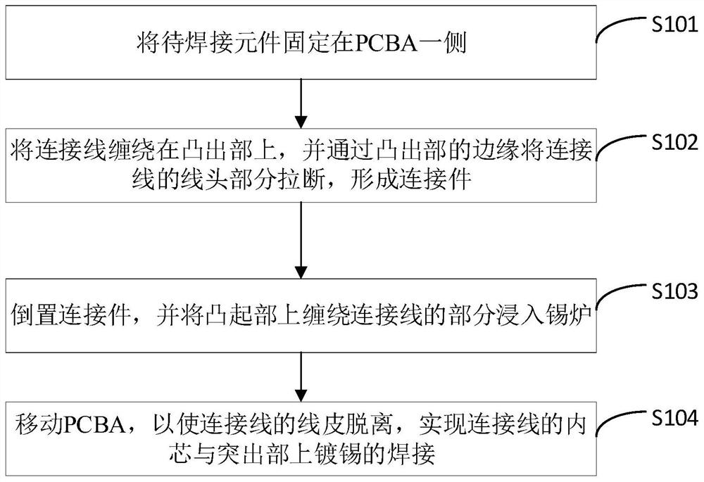
[0046] Embodiment 1 of the present invention discloses a kind of welding method, such as figure 1 shown, including the following steps:

[0047] Step S101, fixing the components to be welded on one side of the PCBA board;

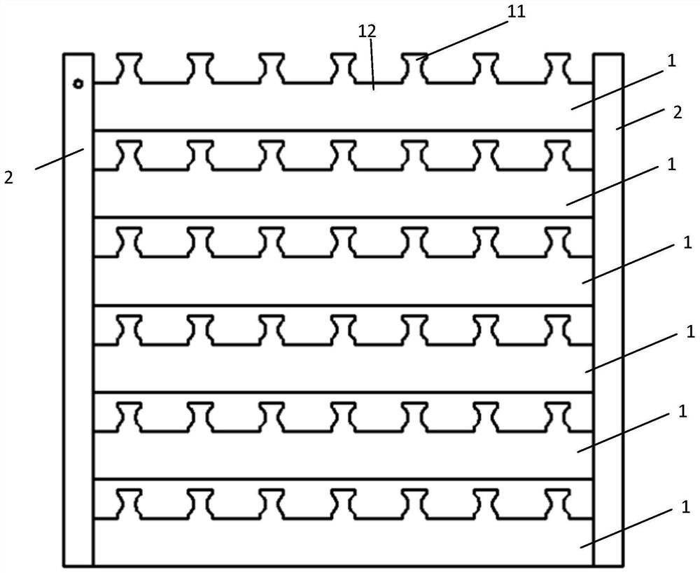
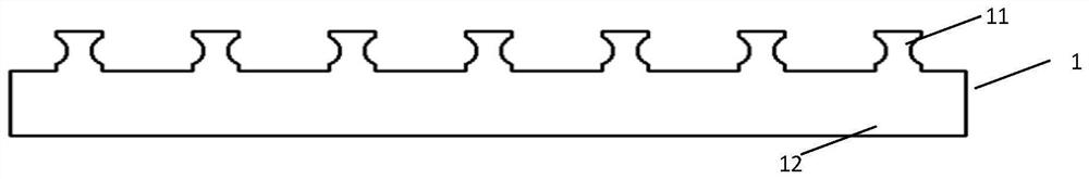
[0048] The component 3 to be welded comprises a component body and a connecting wire 31 with a wire sheath provided on the component body; a PCBA (Printed Circuit Board Assembly, printed circuit board assembly) plate 1 is provided with a tin-plated protrusion 11; The tin plating of the out part 11 is electrically connected with the preset existing electronic components on the PCBA board 1; the top of the component body is lower than the bottom of the protruding part; based on this, since the top of the component body is lower than the bottom of the protruding part, While the portion of the protruding portion 11 around which the connection wire 31 is immersed in the tin liquid after the subsequent inversion, the component body does not come into contact wit...


PUM


Abstract

The embodiment of the invention discloses a welding method. The method comprises the steps that a to-be-welded element is fixed to one side of a PCBA board; a connecting line is wound on a protruding part, the line end part of the connecting line is snapped through the edge of the protruding part, and a connecting piece is formed; the connecting piece is inverted, and the part, wound with the connecting wire, of the protruding part is immersed in the tin liquid; and the PCBA board is moved, so that the wire skin of the connecting wire is separated, and the welding of the inner core of the connecting wire and the tinned part on the protruding part is realized. Compared with an existing scheme, the scheme does not need manual patent leather breaking and thread end cutting, the working procedures are saved, workers do not need high-requirement training and the method is easy to master; the welding area is large, the contact resistance is small, and the product performance is more stable; and the welding strength is high, falling is not prone to occurring, and the reject ratio is reduced.

Description

technical field [0001] The invention relates to the technical field of welding, in particular to a welding method. Background technique [0002] At present, the magnetic ring in the electronic transformer without support needs to be connected to the PCB board. The connection method generally used is welding, and there are two common methods of welding: one is to manually peel the enameled wire on the magnetic ring , and then solder with an electric soldering iron. After the soldering is completed, cut off the excess wire ends; the other is to solder with an electronic spot welder. The specific execution process needs to be tinned at the solder joint position first, and then the enameled wire is used The welding head is pressed on the position of the welding point, and then the high current is used to heat the welding. When the welding is completed, the excess wire needs to be pulled off. [0003] It can be seen that there are some defects in the existing two welding methods...

Claims


Application Information

Patent Timeline
IPC IPC(8): H05K3/34H05K1/18
CPCH05K3/3426H05K1/181H05K2203/04H05K2201/10
Inventor 李锟
Owner 重庆炬特电子有限公司
Why Eureka
Try Eureka