
Vehicle braking and steering system integration test bench

A steering system and integrated testing technology, which is applied in vehicle testing, vehicle steering/bump performance, machine/structural component testing, etc. It can solve problems such as difficulties in coordination of ECU functions, high time cost, and poor repeatability

Active Publication Date: 2021-07-06
JILIN UNIV
View PDF8 Cites 3 Cited by
  • Summary
  • Abstract
  • Description
  • Claims
  • Application Information

AI Technical Summary

Problems solved by technology

The increase of vehicle chassis electronic control systems will bring problems such as coupling conflicts between electronic control systems, increased costs, difficulty in coordinating ECU functions, and waste of computing resources. In order to solve these problems, the integration of chassis electronic control systems is the only way
[0003] However, at present, there is no special hardware-in-the-loop (HIL) bench for the function development, matching and verification of the chassis electronic control system (including electromechanical hydraulic actuators in the loop), and the actual vehicle test has the disadvantages of high time cost, poor economy, low efficiency, Poor repeatability and other shortcomings, once problems occur in the development process of the automobile chassis electronic control system, it is difficult to solve them in time
In addition, the electronic boosters, electronic stability control systems (ESC), and electric power steering systems of most vehicle manufacturers come from different suppliers. When problems occur due to functional interaction, the performance of the vehicle will be reduced, which makes it difficult for vehicle manufacturers Quickly and accurately find the responsible party, hold relevant responsibilities and solve the problem

Method used


Image

  • Vehicle braking and steering system integration test bench
  • Vehicle braking and steering system integration test bench
  • Vehicle braking and steering system integration test bench

Examples


Embodiment Construction

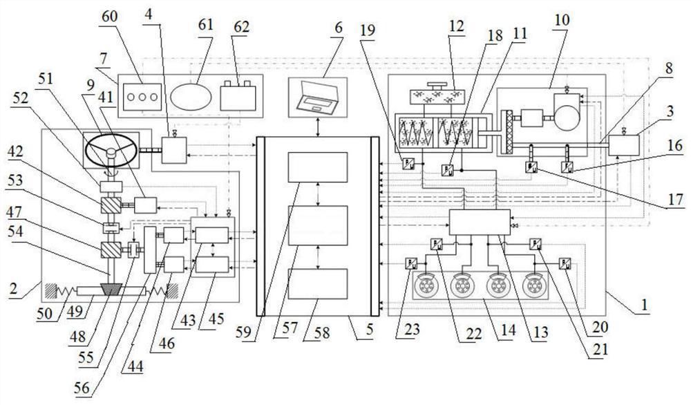
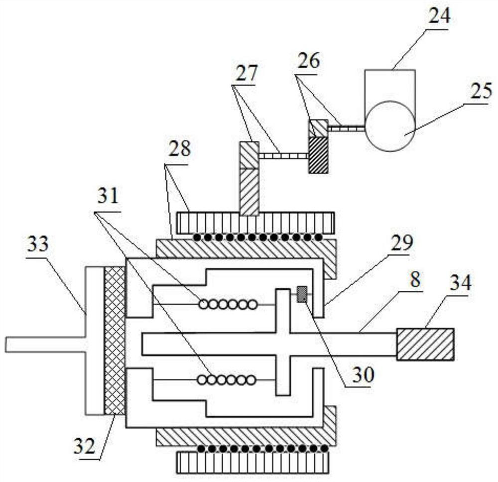
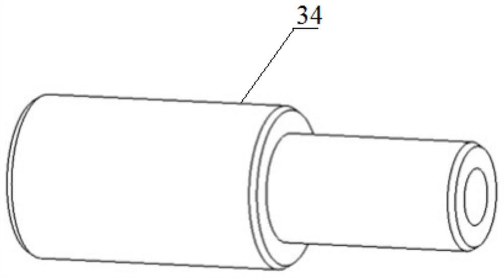
[0055] see Figure 1 to Figure 8 Shown:

[0056] The vehicle brake and steering system integrated test bench provided by the present invention includes a brake-by-wire system 1, a steering-by-wire system 2, an electric cylinder 3, a driving robot 4, a data acquisition and control system 5, a host computer 6 and a power supply system 7, Wherein the electric cylinder 3 is connected with the brake-by-wire system 1 through the input push rod 8, the driving robot 4 is connected with the steering wheel 9 in the steering-by-wire system 2, and the data acquisition and control system 5 is connected with the brake-by-wire system 1 and the electric cylinder respectively. 3. The steering-by-wire system 2 and the driving robot 4 are electrically connected, and the data acquisition and control system 5 respectively collects the sensor signals inside the brake-by-wire system 1, the electric cylinder 3, the steering-by-wire system 2 and the driving robot 4 through the signal acquisition circu...


PUM


Abstract

The invention discloses a vehicle braking and steering system integration test bench, which comprises a wire control braking system, a wire control steering system, an electric cylinder, a driving robot, a data acquisition and control system, an upper computer and a power supply system, and the electric cylinder is connected with the wire control braking system through an input push rod, the driving robot is connected with a steering wheel in the wire control steering system, and the data acquisition and control system is in circuit connection with the wire control braking system, the electric cylinder, the wire control steering system and the driving robot, the data acquisition and control system respectively acquires sensor signals in the wire control braking system, the electric cylinder, the wire control steering system and the driving robot through a signal acquisition circuit, and sends control signals to the wire control braking system, the electric cylinder, the wire control steering system and an ECU (Electronic Control Unit) in the driving robot through a driving circuit, the beneficial effects are that requirements of related regulations and standards can be matched, and dynamic and standardized testing under a braking and steering integrated system can be completed.

Description

technical field [0001] The invention relates to an integrated test bench, in particular to a vehicle brake and steering system integrated test bench. Background technique [0002] At present, with the development of the automobile industry towards electrification, intelligence, and networking, the development trend of the automobile chassis system is: from the traditional mechanical chassis system to the electronic control chassis system. As far as the braking and steering systems are concerned, the electronic booster will replace the vacuum booster to achieve functions such as frictional braking force, regenerative braking, and active pressure building, and the electric power steering system (EPS) will replace the original mechanical steering gear. Power steering, active steering and other functions. The increase of vehicle chassis electronic control systems will bring about problems such as coupling conflicts between electronic control systems, increased costs, difficulty...

Claims


Application Information

Patent Timeline
IPC IPC(8): G01M17/007G01M17/06
CPCG01M17/007G01M17/06
Inventor 朱冰靳万里赵健陈国胜康宇卜纯研李波姜景文
Owner JILIN UNIV
Learn More