Battery monitoring system and method
A technology of battery monitoring system and optical fiber, which is applied in secondary batteries, secondary battery repair/maintenance, circuits, etc., and can solve problems such as in-situ monitoring of dendrites and their growth processes that have not yet been realized
- Summary
- Abstract
- Description
- Claims
- Application Information
AI Technical Summary
Problems solved by technology
Method used
Image

Examples
Embodiment 1
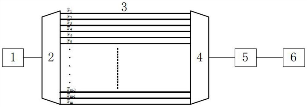
[0041] The monitoring system of this embodiment is suitable for battery in-situ monitoring, such as figure 1 As shown, the monitoring system of this embodiment includes a multi-wavelength light source 1, a wavelength division multiplexer 2, an optical fiber unit 3, a wavelength division multiplexer 4, a spectrum scanner 5, a data acquisition and analysis unit 6, an optical fiber Unit 3 includes m light guiding fibers arranged in parallel, where m is a positive integer.
[0042] This embodiment adopts the wavelength division multiplexing sensing system, and the optical path connection mode of the system is as follows: the output of the multi-wavelength light source 1 is connected to the input end of the wavelength division multiplexer 2, and the wavelength division multiplexer 2 decomposes and connects multiple wavelengths respectively Optical fiber 3 (F 1 ~F m ), optical fiber 3 (F 1 ~F m ) is made with discrete microstructures, the output of each optical fiber is connecte...
Embodiment 2
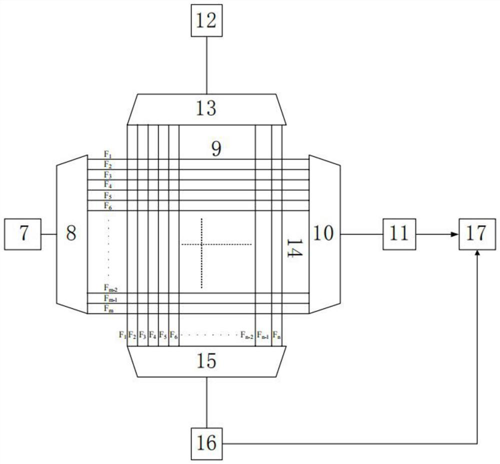
[0048] Such as figure 2 As shown, the monitoring system of this embodiment includes a first multi-wavelength light source 7, a first wavelength division multiplexer 8, a first optical fiber unit 9, a second wavelength division multiplexer 10, a first spectrum scanner 11, A second multi-wavelength light source 12 , a third wavelength division multiplexer 13 , a second optical fiber unit 14 , a fourth wavelength division multiplexer 15 , a second spectrum scanner 16 , and a data acquisition and analysis unit 17 . The first light guiding fiber unit 9 includes m light guiding fibers arranged in parallel in the horizontal direction, and the second light guiding fiber unit 14 includes n light guiding fibers arranged in parallel in the vertical direction, where m and n are positive integers.
[0049] The connection mode of the system optical path for sensing in this embodiment is as follows:
[0050] In the horizontal direction, the output terminal of the first multi-wavelength lig...
Embodiment 3
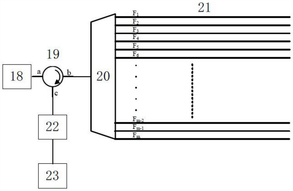
[0057] The system structure of this case includes a third multi-wavelength light source 18 , a first circulator 19 , a fifth wavelength division multiplexer 20 , a third optical fiber unit 21 , a third spectrum scanner 22 , and a data acquisition and analysis unit 23 . The third light guiding fiber unit includes m light guiding fibers arranged in parallel in the horizontal direction.
[0058] The specific implementation steps of this case for sensing are as follows:
[0059] The system optical path connection mode is as follows: the output of the third multi-wavelength light source 18 is connected to the first circulator 19a port, and the circulator 19b port is connected to the input end of the fifth wavelength division multiplexer 20, and the fifth wavelength division multiplexer 20 connects multiple The wavelengths are decomposed respectively to connect the optical fiber 21 (F 1 ~F m ), optical fiber 21 (F 1 ~F m ) is made with a discrete microstructure, the port of the ...
PUM
| Property | Measurement | Unit |
|---|---|---|
| Diameter | aaaaa | aaaaa |
Abstract
Description
Claims
Application Information
 - R&D
- Intellectual Property
- Life Sciences
- Materials
- Tech Scout
- Unparalleled Data Quality
- Higher Quality Content
- 60% Fewer Hallucinations
Browse by: Latest US Patents, China's latest patents, Technical Efficacy Thesaurus, Application Domain, Technology Topic, Popular Technical Reports.
© 2025 PatSnap. All rights reserved.Legal|Privacy policy|Modern Slavery Act Transparency Statement|Sitemap|About US| Contact US: help@patsnap.com