A device and method for measuring workpiece defects based on Rydberg atoms

A technology of measuring device and measuring method, which is applied in the direction of measuring device, transmittance measurement, optical device, etc., to achieve the effect of benefiting equipment integration, simple measurement operation, and real-time online feedback

Active Publication Date: 2022-03-18
SHANXI UNIV
View PDF0 Cites 0 Cited by
  • Summary
  • Abstract
  • Description
  • Claims
  • Application Information

AI Technical Summary

Problems solved by technology

[0005] The present invention overcomes the deficiencies in the prior art, and the technical problem to be solved is to provide a workpiece defect based on Rydberg atoms that is highly sensitive, pollution-free, can be used for workpiece surface and internal detection, has low environmental requirements and is simple to operate Measuring device and method

Method used


Image

  • A device and method for measuring workpiece defects based on Rydberg atoms
  • A device and method for measuring workpiece defects based on Rydberg atoms
  • A device and method for measuring workpiece defects based on Rydberg atoms

Examples


Embodiment 1

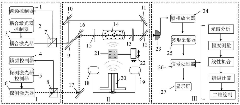
[0035] Such as figure 1 As shown, Embodiment 1 of the present invention provides a workpiece defect measurement device based on Rydberg atoms, including a detection light source, a coupling light source, an alkali metal atom gas cell 14, a first light guide device, a second light guide device, and a second light guide device. A radio frequency signal source 18, a second radio frequency signal source 19, a waveguide 20, a workpiece carrying mechanism 22 to be measured, a photoelectric detector 23 and a data acquisition and processing module; A light-guiding device and a second light-guiding device are oppositely coincident and incident on the alkali metal atom gas chamber 14 for exciting the atoms to the Rydberg state; the first radio-frequency signal source 18 and the second radio-frequency signal source 19 The signal output end is connected with the waveguide 20, and is used to output microwave signals with frequency difference respectively. After the microwave signal passes ...

Embodiment 2

[0059] Embodiment 2 of the present invention provides a measurement method of a workpiece defect measurement device based on Rydberg atoms, comprising the following steps:

[0060] S1. Obtain the relationship between the electric field strength of the transmission signal and the crack width.

[0061] Among them, the specific method to obtain the relationship between the electric field intensity of the transmission signal and the crack width is as follows:

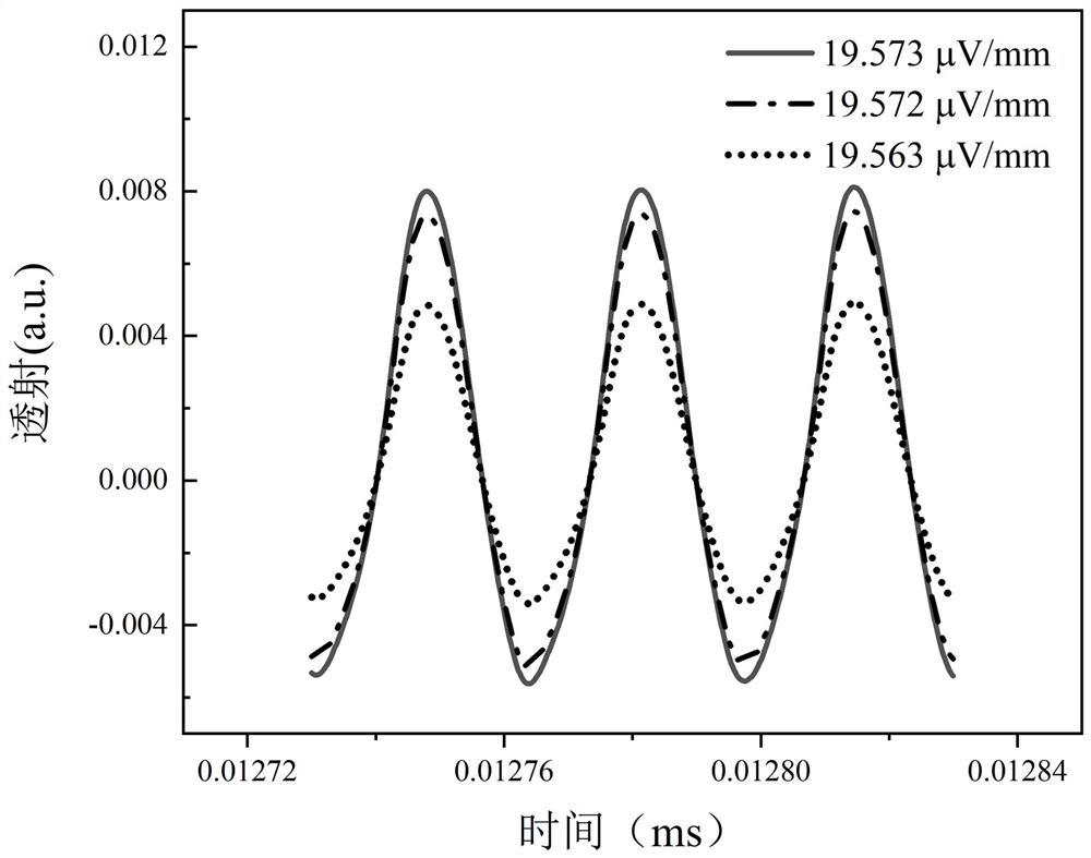
[0062] Set a plurality of calibration samples with known crack widths, set the calibration samples at the waveguide 20, make the microwave signal emitted by the waveguide 20 interact with the Rydberg atoms after passing through each crack of the calibration sample, and collect the probe light through the Rydberg atoms According to the different slit widths and the corresponding electric field strengths of the transmission signals, the final transmission signals are fitted by the least squares method to obtain the relationsh...


PUM


Abstract

The invention belongs to the technical field of workpiece defect measurement, and discloses a workpiece defect measurement device based on Rydberg atoms, which includes a detection light source and a coupling light source, and the detection light and coupling light emitted by the detection light source and the coupling light source overlap and incident on alkali metal atoms The gas chamber excites the atoms to the Rydberg state; the signal output ends of the first radio frequency signal source and the second radio frequency signal source are connected to the waveguide for respectively outputting microwave signals with frequency differences, and the microwave signals are sent out by the waveguide and then incident on the alkali The metal atom gas chamber interacts with the Rydberg atoms; the photodetector receives the detection light after passing through the alkali metal atom gas chamber and sends it to the data acquisition and processing module, and the data acquisition and processing module calculates the defects of the workpiece to be tested according to the intensity of the detection light . The invention can realize the curve measurement of the workpiece, has high measurement precision and simple measurement operation.

Description

technical field [0001] The invention belongs to the technical field of workpiece defect measurement, and in particular relates to a device and method for measuring workpiece defects by using Rydberg atoms. Background technique [0002] With the increase of the service life of many workpieces and the impact of the environment on the workpiece to varying degrees, the measurement of workpiece defects has become an important task. Whether the defects of the workpiece can be accurately measured plays an important role in the repair and reuse of the workpiece. [0003] In the current field of workpiece defect measurement, the defect measurement methods are mainly divided into two parts: human eye recognition by quality inspection staff and traditional contact measurement. The traditional manual quality inspection is inefficient and labor-intensive, and its inspection results are greatly affected by the subjective factors of the quality inspection staff, and the situation of false...

Claims


Application Information

Patent Timeline
Patent Type & Authority Patents(China)
IPC IPC(8): G01N21/59G01N22/02G01B11/02G01B15/00
CPCG01N21/59G01N22/02G01B11/02G01B15/00
Inventor 元晋鹏汪丽蓉靳婷
Owner SHANXI UNIV
Why Eureka
Try Eureka