
Wafer defect cross-section observation device

An observation device and wafer technology, applied in semiconductor/solid-state device testing/measurement, etc., can solve the problems of cutting, difficult to control precision, low precision, etc., and achieve the effect of convenient operation, simple process and high precision

Active Publication Date: 2015-11-25
SHANGHAI HUALI MICROELECTRONICS CORP
View PDF4 Cites 0 Cited by
  • Summary
  • Abstract
  • Description
  • Claims
  • Application Information

AI Technical Summary

Problems solved by technology

This method of observing the cut surface of the wafer through a scanning electron microscope and using a high-energy ion beam to cross-cut the wafer is time-consuming and labor-intensive, and the accuracy is difficult to control.
[0004] Therefore, it is the need of the present invention to solve the complex process and low precision problems caused by switching the focused ion gun and the scanning electron microscope to realize cutting the wafer and observing the cut surface while analyzing the wafer defect in the prior art. Technical issues resolved

Method used


Image

  • Wafer defect cross-section observation device
  • Wafer defect cross-section observation device
  • Wafer defect cross-section observation device

Examples


Embodiment Construction

[0016] The specific embodiments of the present invention will be further described in detail below with reference to the accompanying drawings.

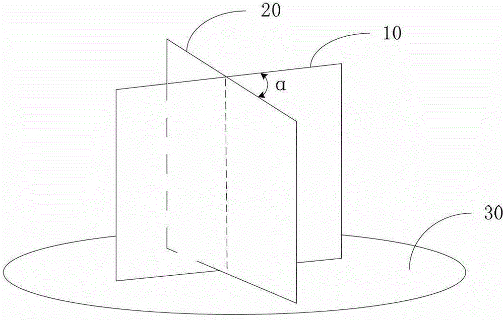
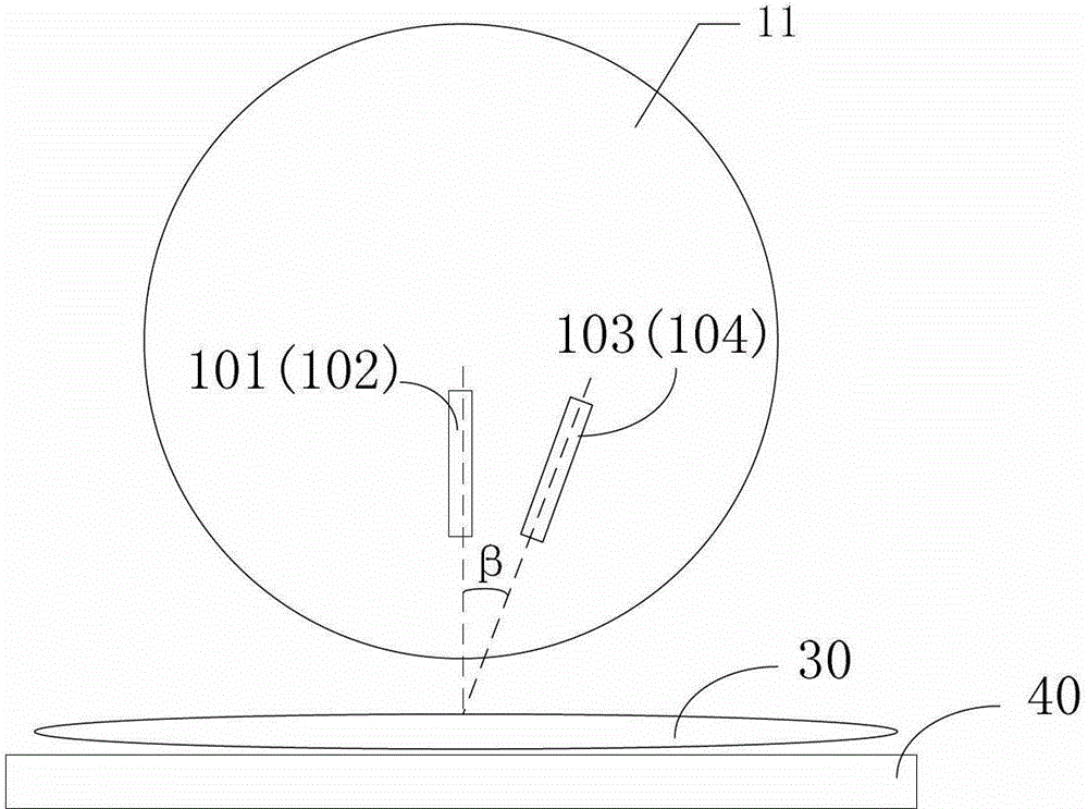
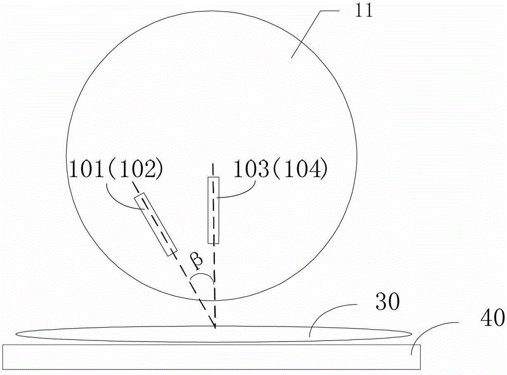
[0017] Such as figure 1 , Figure 2A-2B with image 3 As shown, the wafer defect cross-cut observation device provided by the embodiment of the present invention is applied to cross-cut a wafer at a defect and observe the defect morphology of the cut surface in the field of semiconductor processing.

[0018] The bottom of the wafer defect cross-cutting observation device can be provided with a mounting table 40 for placing the wafer to be inspected. The device specifically includes: a focused ion gun 101, which is arranged in a first plane 10 perpendicular to the wafer surface 30, and is used to inject a high-energy ion beam on the wafer surface 30 to cut the wafer to form a wafer section; and a scanning electron gun 103, which is arranged The position in the first plane is different from that of the focused ion gun 101, and is used to in...


PUM


Abstract

The invention relates to a wafer defect crosscutting observation device which comprises a focusing ion gun, a scanning electronic gun, a focusing ion microscope, a scanning electronic microscope, a light source emitter and an optical imaging unit. The focusing ion gun is arranged in a first plane which is perpendicular to the surface of a wafer. The scanning electronic gun is arranged at the position, different from the position of the focusing ion gun, in the first plane, and a first angle included angle is formed between the emitting direction of the scanning electronic gun and the emitting direction of the focusing ion gun. The focusing ion microscope and the focusing ion gun are integrally arranged in the first plane. The scanning electronic microscope and the scanning electronic gun are integrally arranged in the first plane. The light source emitter is arranged in a second plane which is perpendicular to the surface of the wafer. The optical imaging unit is arranged in the second plane, and a second angle included angle is formed between the optical path direction of the optical imaging unit and the direct of incident beams of the light source emitter. An included angle larger than zero degree is formed between the second plane and the first plane. The wafer defect crosscutting observation device can directly achieve positioning of wafer defects, simultaneous crosscutting and observation and even analysis, working processes are simple, operation is convenient, and precision is higher.

Description

Technical field [0001] The invention relates to the field of semiconductor processing, and more specifically, to a wafer defect cross-cut observation device. Background technique [0002] The focused ion beam slicing machine commonly used in the semiconductor industry is an indispensable observation device in semiconductor R&D and manufacturing. Its main purpose is to cross-cut wafers to display defect locations and view cross-sectional views of stacked layers. [0003] At present, for defects in the front layer of the wafer, it is necessary to find the defect location on other inspection machines (such as a visual inspection machine with an optical microscope), remember the specific information of the peripheral topography, and then send the wafer to the microtome , Look for the previously memorized topography for cross sectioning; or use a scanning electron gun and a scanning electron microscope to bombard a point with an electron beam to artificially create a burnmark, and perfo...

Claims


Application Information

Patent Timeline
Patent Type & Authority Patents(China)
IPC IPC(8): H01L21/66
Inventor 郭贤权许向辉顾珍
Owner SHANGHAI HUALI MICROELECTRONICS CORP
Learn More