Separator for lithium metal battery and preparation method thereof

A technology for lithium metal batteries and separators, which is applied to lithium batteries, secondary batteries, battery pack components, etc., can solve the problems of battery gas production and capacity reduction, lithium battery short circuit, electrolyte side reactions, etc., and improve battery safety. Sexuality, reduce energy decay, reduce side effects

Active Publication Date: 2021-10-08
JIANGSU ADVANCED MATERIAL TECH CO LTD
View PDF6 Cites 0 Cited by
  • Summary
  • Abstract
  • Description
  • Claims
  • Application Information

AI Technical Summary

Problems solved by technology

[0005] The technical problem to be solved by the present invention is: to solve the lithium dendrite formed by the precipitation of metal lithium in the metal lithium battery in the prior art. The lithium dendrite has a large surface area and is prone to side reactions with the electrolyte, resulting in gas production and capacity reduction of the battery, and further , lithium dendrites may pierce the separator, leading to technical problems of short circuit and combustion explosion of lithium batteries

Method used


Image

  • Separator for lithium metal battery and preparation method thereof
  • Separator for lithium metal battery and preparation method thereof
  • Separator for lithium metal battery and preparation method thereof

Examples


preparation example Construction

[0032] The preparation method for the separator of lithium metal battery as above, comprises the following steps:

[0033] S1. Sanding and mixing the conductive agent 31 and the piezoelectric ceramic particles 32 to obtain coating powder;

[0034] S2. Mix the coating powder and binder evenly, add additive CMC and wetting agent BYK-346 to prepare composite slurry;

[0035] S3, coating the composite slurry on the surface of the lithium metal battery separator body 3 .

[0036] working principle:

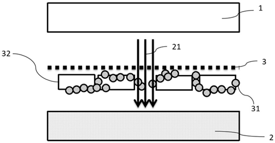
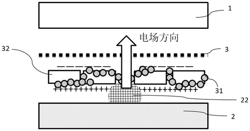
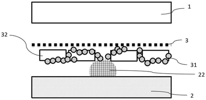
[0037] Lithium ions 21 move from the positive electrode 1 to the negative electrode 2 during charging, forming a charging current. Due to the non-uniform microstructure, the charging current is also non-uniform. Such as Figure 1 to Figure 3 As shown, when the coating separator has a large hole, an excessive charging current will appear here, and if lithium ions 21 are too late to enter the negative electrode 2, lithium metal deposition 22 will occur on the surface of the negative ...

Embodiment 1

[0039]The conductive agent 31 is conductive carbon black, the binder is 40% solid content styrene-butadiene rubber emulsion and CMC, and the piezoelectric ceramic particles 32 are barium titanate. The particle size D50 of barium titanate is 1.2 microns. Conductive agent 31, barium titanate, and deionized water were sand-milled and mixed uniformly at a mass ratio of 2:8:40, and then dried to obtain coating powder. Mix the coating powder, styrene-butadiene rubber emulsion, CMC, wetting agent BYK-346 and deionized water evenly according to the mass ratio of 30:4:0.15:0.1:65.75. Coat on a 9 micron membrane (manufactured by TNS) using a microgravure and dry. The thickness of the piezoelectric ceramic coating is 2 microns after drying.

Embodiment 2

[0041] The difference from Example 1 is that the barium titanate particle size is 0.5 micron, and the coating thickness is 1 micron.


PUM

PropertyMeasurementUnit
thicknessaaaaaaaaaa
particle diameteraaaaaaaaaa
thicknessaaaaaaaaaa

Abstract

The invention relates to the technical field of lithium batteries, in particular to a separator for lithium metal batteries and a preparation method thereof. A diaphragm for lithium metal batteries, comprising a diaphragm body, at least one side of the diaphragm body is coated with a piezoelectric ceramic layer with piezoelectric properties, and the side of the diaphragm body coated with the piezoelectric ceramic layer faces the negative electrode of the lithium metal battery, The electroceramic layer is composed of conductive agent, binder and piezoelectric ceramic particles. A separator for a lithium metal battery of the present invention can enable uniform deposition of lithium ions during the reaction process, and the uniformly precipitated lithium has a smaller surface area than dendritic lithium, which can reduce side reactions and slow down the performance decay of lithium batteries. Moreover, the uniformly deposited lithium will not pierce the separator and cause a short circuit, which improves the safety of the battery.

Description

technical field [0001] The invention relates to the technical field of lithium batteries, in particular to a separator for lithium metal batteries and a preparation method thereof. Background technique [0002] Lithium-ion batteries are composed of winding or stacking basic unit structures, and the basic unit structure is positive electrode / separator / negative electrode. Among them, the positive electrode and the negative electrode are the place where the electrochemical reaction occurs. The current generated by the electrochemical reaction is collected and exported through the current collector in the positive electrode and the negative electrode; the separator is responsible for separating the positive electrode and the negative electrode to avoid the short circuit of the positive and negative electrodes. . [0003] During the charging process of a lithium battery, lithium ions are deintercalated from the positive electrode active material, conducted in the electrolyte, an...

Claims


Application Information

Patent Timeline
Patent Type & Authority Patents(China)
IPC IPC(8): H01M50/434H01M50/446H01M50/449H01M50/403H01M10/052H01M10/42
CPCH01M10/052H01M10/4235Y02E60/10
Inventor 张磊王晓明徐强陈伦杨浩田戴静闻包慧
Owner JIANGSU ADVANCED MATERIAL TECH CO LTD
Why Eureka
Try Eureka