Unlock instant, AI-driven research and patent intelligence for your innovation.
Vision-laser radar fusion method and system based on depth canonical correlation analysis
What is Al technical title?
Al technical title is built by PatSnap Al team. It summarizes the technical point description of the patent document.
A typical correlation analysis and lidar technology, applied in the field of vision-lidar fusion, can solve problems such as short boards, detection system failures, negatives, etc., and achieve the effect of improving accuracy
Active Publication Date: 2021-07-13
TSINGHUA UNIV
View PDF11 Cites 11 Cited by
Summary
Abstract
Description
Claims
Application Information
AI Technical Summary
This helps you quickly interpret patents by identifying the three key elements:
Problems solved by technology
Method used
Benefits of technology
Problems solved by technology
However, both sensors have certain drawbacks
For cameras, RGB images, as a dense 2D representation, express spatial information through pixel positions and pixel values, and compress the depth information of the Z axis, which makes it difficult to predict the absolute position of objects in space in 3D target detection tasks. ; In addition, the camera lens is also very sensitive to changes in light, often overexposed or too dark, the data collected in this scene is difficult to identify, missing effective information
For lidar, although the precise spatial position information of the target can be obtained, as an active sensor, lidar can only accept the lasersignal emitted by the sensor, and cannot accept the signal reflected by the object through visible light, so the color of the object cannot be obtained. Texture and other feature information; moreover, the wavelength of the laser is very short, which makes the lidar data very sensitive to special weather. For example, the lidar point cloud obtained in rainy and snowy weather usually has a lot of noise
[0006] To sum up, if images are used as the main input information, the detection system will suffer serious failures when image information is missing due to changes in lighting conditions. In addition, the lack of spatial distance information in images also causes shortcomings in detection.
Although the lidar point cloud can overcome the problem of illumination changes, the sparseness and disorder of the point cloud also limit its detection ability. It is likely that small objects beyond 100 meters cannot be detected, which is not conducive to the speed of the car at high speed. perception
Therefore, in order to solve the problem of insufficient detection ability when using only on-board cameras or lidar, a novel idea is to consider combining more sensors and perform data fusion to improve the ability to perceive the environment
However, a large number of experiments at this stage have shown that if the pixel-level fusion of the point cloud information obtained by the lidar and the RGB image obtained by the camera is simply performed, not only will it not improve the accuracy of the perceptionalgorithm, but it will have a negative effect. Reduces perception accuracy to a certain extent
Method used
Image
Click on the blue label to locate the original text in one second.
Reading with bidirectional positioning of images and text.
Examples
Embodiment 1
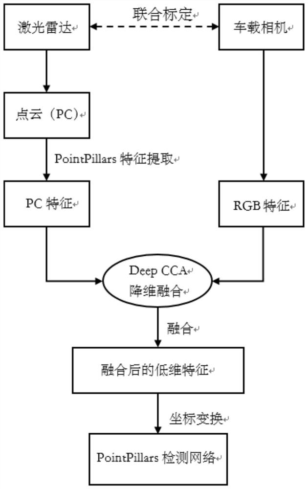
[0059] Such as figure 1 As shown, Embodiment 1 of the present invention provides a vision-lidar fusion method based on deep canonical correlation analysis, including the following steps:
[0060] Step 1. Collect the lidar point cloud and camera images in the autonomous driving scene. By default, the calibration and alignment have been completed. Since the verification of the algorithm must ensure that it is open and effective, relevant experiments are carried out in the public data set KITTI.
[0061] Step 2. Fusion of lidar point cloud data and RGB data.
[0062] 1) The original lidar data is a point cloud. The point cloud in KITTI can be expressed as a matrix of [N, 4], where N is the number of point clouds in a frame scene, and the four-dimensional features of each point [x, y, z, i], respectively, the space x, y, z coordinates and the laser reflection intensity i;
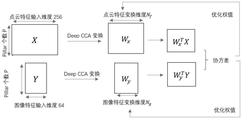
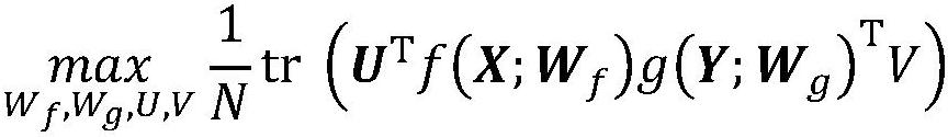
[0063] 2) Given 2 sets of N vectors: x represents image features, and y represents point cloud features. ...
Embodiment 2
[0079] Embodiment 2 of the present invention provides a vision-lidar fusion system based on deep canonical correlation analysis, the system includes: a pre-established and trained fusion model, an acquisition module, an RGB feature extraction module, and a point cloud feature extraction module , fusion output module and target detection module; where,
[0080] The collection module is used to synchronously collect RGB images and point cloud data of the road surface;
[0081]The RGB feature extraction module is used to perform feature extraction on RGB images to obtain RGB features;
[0082] The point cloud feature extraction module is used to sequentially perform coordinate system conversion and rasterization processing on the point cloud data, and then perform feature extraction to obtain point cloud features;
[0083] The fusion output module is used to input point cloud features and RGB features into a pre-established and trained fusion model at the same time, and output f...
Embodiment 3
[0086] A computer device includes a memory, a processor, and a computer program stored on the memory and operable on the processor, and the method of Embodiment 1 is implemented when the processor executes the computer program.
PUM
Abstract
The invention relates to the technical field of automatic driving, in particular to a vision-laserradar fusion method and system based on deep canonical correlation analysis. The method comprises the following steps: synchronously acquiring an RGB image and point cloud data of a road surface; performing feature extraction on the RGB image to obtain RGB features; sequentially performing coordinate system conversion and rasterization processing on the point cloud data, and then performing feature extraction to obtain point cloud features; inputting the point cloud features and the RGB features into a pre-established and trained fusion model at the same time, outputting feature-enhanced fusion point cloud features, and fusing, by the fusion model, the RGB features into the point cloud features by using correlation analysis in combination with a deep neural network; and inputting the fused point cloud features into a pre-established target detection network to realize target detection. The depth canonical correlationanalysis method is creatively used, and the similarity calculation matrix is utilized to fuse two different modal features of the point cloud and the image, so that the precision is improved under the condition of necessary speed compromise.
Description
technical field [0001] The invention relates to the technical field of automatic driving, in particular to a vision-lidar fusion method and system based on deep canonical correlation analysis. Background technique [0002] In recent years, the field of autonomous driving technology has developed rapidly, in which environmental perception technology is an indispensable part. Self-driving vehicles rely on sensors such as lidar, camera, and millimeter-wave radar to perceive the surrounding environment, and collect and process environmental information and in-vehicle information, mainly involving technologies such as road boundary monitoring, vehicle detection, and pedestrian detection. Environmental perception can feed back real-time road information to the car, so as to provide more precise control of the driving behavior of the vehicle, thereby improving driving safety and comfort. [0003] As one of the basic functions of the automatic driving system, 3D object detection ca...
Claims
Application Information
Patent Timeline
Application Date:The date an application was filed.
Publication Date:The date a patent or application was officially published.
First Publication Date:The earliest publication date of a patent with the same application number.
Issue Date:Publication date of the patent grant document.
PCT Entry Date:The Entry date of PCT National Phase.
Estimated Expiry Date:The statutory expiry date of a patent right according to the Patent Law, and it is the longest term of protection that the patent right can achieve without the termination of the patent right due to other reasons(Term extension factor has been taken into account ).
Invalid Date:Actual expiry date is based on effective date or publication date of legal transaction data of invalid patent.

