A fuel cell catalytic layer slurry and its preparation method and application

A fuel cell and catalytic layer technology, applied in fuel cells, battery electrodes, electrochemical generators, etc., can solve problems such as unsuitable for large-scale production, poor dispersion of carbon nanotubes, poor performance of membrane electrodes, etc., to reduce total platinum The effects of loading capacity, optimizing pore structure, reducing contact resistance and mass transfer resistance

Active Publication Date: 2022-01-28
STATE POWER INVESTMENT CORP HYDROGEN ENERGY CO LTD
View PDF21 Cites 0 Cited by
  • Summary
  • Abstract
  • Description
  • Claims
  • Application Information

AI Technical Summary

Problems solved by technology

[0005] The present invention is based on the discovery and understanding of the following facts and problems: although it is proposed in the related art to add carbon nanotubes to the catalytic layer of the fuel cell, which improves the performance of the membrane electrode to a certain extent, but due to failure to solve the problem of carbon nanotubes The problem of poor dispersion of nanotubes, the performance of the prepared membrane electrode is poor, and it is prepared by spraying process, the efficiency is low, and it is not suitable for large-scale production

Method used


Image

  • A fuel cell catalytic layer slurry and its preparation method and application
  • A fuel cell catalytic layer slurry and its preparation method and application
  • A fuel cell catalytic layer slurry and its preparation method and application

Examples


preparation example Construction

[0034] The embodiment of the present invention also proposes a method for preparing fuel cell catalyst layer slurry, which includes the following steps:

[0035] a, mixing carbon nanotubes, graphene and dispersant uniformly to obtain the first slurry mixture;

[0036]b, adding deionized water to the Pt / C catalyst to wet the catalyst, after mixing evenly, adding the solvent and the first slurry mixture obtained in step a in sequence, and performing ball milling to obtain the second slurry mixture;

[0037] c. Add a perfluorosulfonic acid resin solution to the second slurry mixture obtained in step b, and perform ball milling to obtain a catalytic layer slurry.

[0038] According to the preparation method of fuel cell catalyst layer slurry in the embodiment of the present invention, carbon nanotubes and graphene are mixed in advance to form the first slurry mixture, and a dispersant is added during the mixing process to make carbon nanotubes and graphene Can be well dispersed, ...

Embodiment 1

[0047] 1. Preparation of fuel cell catalyst layer slurry

[0048] 2.5 parts by weight of carbon nanotubes, 2.5 parts by weight of graphene and 2.5 parts by weight of dispersant polyvinyl alcohol are mixed and stirred evenly to obtain the first slurry mixture; 100 parts by weight of Pt / C (50%) catalyst is weighed and put into a ball mill In the tank, use a dropper to add 250 parts by weight of deionized water to fully wet the catalyst. After mixing evenly, add 800 parts by weight of n-propanol and the pre-mixed first slurry mixture in sequence, and add 500 parts by weight of zirconia grinding balls , after the ball milling tank is sealed, put it into an automatic ball mill for ball milling, the rotating speed is 300r / min, and the ball milling time is 4h to obtain the second slurry mixture; then take out the ball milling tank, and add 80 parts by weight to the second slurry mixture slurry For the perfluorosulfonic acid resin, the perfluorosulfonic acid resin was prepared into a ...

Embodiment 2

[0057] The preparation method is the same as in Example 1, except that the proportion of the catalyst layer slurry is different, specifically 100 parts by weight of Pt / C catalyst, 250 parts by weight of deionized water, 750 parts by weight of n-propanol, and 100 parts by weight of ethanol , 4 parts by weight of carbon nanotubes, 1 part by weight of graphene, 5 parts by weight of dispersant polyacrylic acid and 70 parts by weight of perfluorosulfonic acid resin.

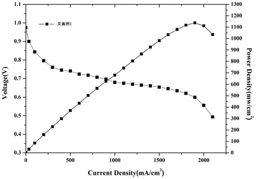
[0058] The battery made in this embodiment has a current density of 900mA / cm at 0.7V 2 , at 0.6V, the current density is 1800mA / cm 2 , the maximum power density can reach 1120mw / cm 2 .


PUM

PropertyMeasurementUnit
current densityaaaaaaaaaa

Abstract

The invention discloses a fuel cell catalytic layer slurry, which comprises 100 parts by weight of Pt / C catalyst, 500-1000 parts by weight of solvent, 2-4 parts by weight of carbon nanotubes, 1-3 parts by weight of graphene, 2-5 parts by weight of Parts by weight of dispersant and 65-105 parts by weight of perfluorosulfonic acid resin. The present invention also discloses a preparation method of fuel cell catalyst layer slurry, which includes: a. uniformly mixing carbon nanotubes, graphene and dispersant to obtain the first slurry mixture; b. adding deionized water to the Pt / C catalyst After mixing, add the solvent and the first slurry mixture in sequence, and ball mill to obtain the second slurry mixture; c, add perfluorosulfonic acid resin solution to the second slurry mixture, and ball mill to obtain the catalytic layer slurry. The fuel cell catalytic layer slurry of the present invention improves the pore structure of the catalytic layer by constructing a multi-dimensional carbon material network, improves the utilization rate of the catalyst, and produces a membrane electrode with excellent performance, which is suitable for low humidification vehicle working conditions.

Description

technical field [0001] The invention belongs to the technical field of fuel cells, and in particular relates to a fuel cell catalyst layer slurry, in particular to a preparation method of the fuel cell catalyst layer slurry, and further to an application of the fuel cell catalyst layer slurry. Background technique [0002] The membrane electrode assembly is the core component of the fuel cell, and the catalytic layer is an important part of the membrane electrode assembly, which is crucial to the cost and performance of the proton membrane fuel cell. In order to improve the performance of the catalytic layer, the proton conductivity of the catalyst is usually improved by introducing ordered carbon materials as the support of the Pt catalyst. However, the complexity of the manufacturing process will lead to increased costs, and it is not suitable for industrial applications. [0003] In the related art, CN106076330A discloses a method for preparing a coating slurry of a cata...

Claims


Application Information

Patent Timeline
Patent Type & Authority Patents(China)
IPC IPC(8): H01M4/92H01M4/90H01M4/88H01M8/1004
CPCH01M4/926H01M4/9008H01M4/8828H01M4/8882H01M8/1004Y02E60/50
Inventor 耿凯明江胜娟周明正
Owner STATE POWER INVESTMENT CORP HYDROGEN ENERGY CO LTD
Why Eureka
Try Eureka