
Oscillator antenna

A vibrator antenna and line technology, applied in antennas, antenna coupling, antenna arrays, etc., can solve the problems that the vibrator cannot meet the radiation performance requirements of the 5G antenna, the requirements for the size accuracy of the vibrator are getting higher and higher, and the coverage capability of a single base station is weakened. The effect of increasing the bandwidth, increasing the cross-polarization ratio, and reducing the area

Pending Publication Date: 2021-07-20
SHENZHEN SUNWAY COMM +1
View PDF0 Cites 0 Cited by
  • Summary
  • Abstract
  • Description
  • Claims
  • Application Information

AI Technical Summary

Problems solved by technology

[0002] After entering the 5G era, on the one hand, as the frequency band of the 5G network moves up, the coverage capability of a single base station will weaken, resulting in an increase in the number of base stations and a significant increase in the number of antennas used. It is predicted that the total number of 5G base stations will be 1.3 to 1.5 times the number of 4G base stations. The number of vibrators contained in the antenna will be greatly increased, from 2-18 vibrators in the original antenna, to 64, 128, or even 256. In the prior art, the use of metal materials to make vibrator antennas will lead to a significant increase in weight , which leads to problems such as high cost and inconvenient installation; on the other hand, the 5G operating frequency is getting higher and higher, the wavelength is getting shorter and shorter, and the requirements for the dimensional accuracy of the oscillator are getting higher and higher, and the 5G communication rate is higher. Traditional The electrical performance of the vibrator can no longer meet the radiation performance requirements of 5G antennas
[0003] Therefore, with the development of 5G, the weight, cost and electrical performance of traditional dipole antennas are facing great challenges

Method used


Image

  • Oscillator antenna
  • Oscillator antenna
  • Oscillator antenna

Examples


Embodiment 1

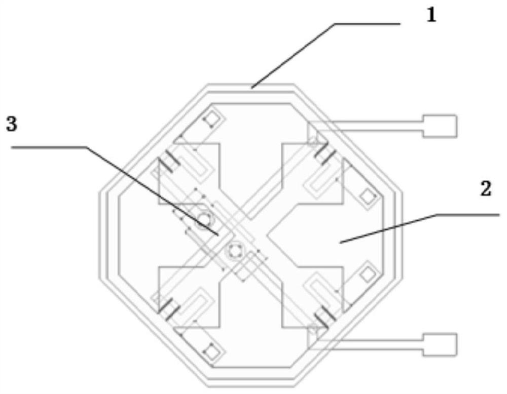
[0071] Please refer to Figure 1-Figure 4 , a dipole antenna, comprising: a radiator 1, a feed network 3 and a substrate;

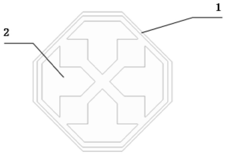
[0072] Such as figure 2 As shown, the radiation sheet 1 includes four boat-shaped openings 2;

[0073] Wherein, under the premise of ensuring good overall performance of the antenna, the radiation sheet 1 adopts more economical materials, preferably, a PCB board made of low-cost FR4 material can be used, for the convenience of assembly, as figure 1 As shown, the PCB board is chamfered adaptively, wherein the four boat-shaped openings 2 are evenly distributed around the center of the radiation sheet 1, and two pairs are symmetrical about the center of the radiation sheet 1;

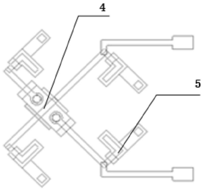
[0074] Such as figure 2 As shown, the feed network 3 includes 2 differential lines 4 and 4 L-shaped lines 5;

[0075] Wherein, the differential line 4 connects the two L-shaped lines 5 located at the opposite corners in combination, the line length phase difference corresponding...

Embodiment 2

[0082] In this embodiment, on the basis of the first embodiment above, the manner of connecting the substrate 9 and the radiation sheet 1 is further limited;

[0083] Please refer to Figure 4 with Figure 5 , the substrate 9 includes a support platform 7;

[0084] The support platform 7 includes a heat-melt column 8;

[0085] The support table 7 is fixedly connected to the radiation sheet 1 through the heat-melt column 8;

[0086] Wherein, the radiation sheet 1 is provided with a through hole corresponding to the heat-melt column 8, and the heat-melt column 8 passes through the through hole, and the radiation sheet can be fastened by heat-melting the heat-melt column 8 1. The height of the radiation sheet 1 can be guaranteed, and the hot-melt can be controlled automatically, which can reduce the labor cost to a certain extent;

[0087] The substrate 9 is made of plastic material and is integrally injection molded;

[0088] The feed network 3 is processed by electroplatin...

Embodiment 3

[0092] In this embodiment, on the basis of Embodiment 1 or Embodiment 2, the form of the dipole antenna is further limited;

[0093] The number of the radiating sheet 1 and its corresponding feeding network 3 and supporting platform 7 is multiple, and they are arranged in order such as 1×2, 1×3 or 1×4 to form a vibrator unit group, and a plurality of dipole unit groups are arranged in order Arrange in order to form a dipole antenna array, for example, arrange dipole unit groups to form large-scale low The cross-sectional antenna array is convenient for production and assembly through the array method, and it is also convenient for disassembly and maintenance, which improves production efficiency and reduces maintenance costs. It is especially suitable for 5G large-scale antenna arrays to realize Massive MIMO technology and beamforming technology;

[0094] In an alternative embodiment, such as Image 6 As shown, the number of the radiation sheets is 3 and arranged horizontally...


PUM


Abstract

The invention discloses an oscillator antenna, which comprises a radiation sheet, a feed network and a substrate, the radiation sheet comprises four ship-shaped holes; the feed network comprises two differential lines and four L-shaped lines; every two L-shaped circuits are combined and connected through the differential circuits; the L-shaped lines are distributed below the connecting positions of the adjacent ship-shaped open holes in a one-to-one correspondence mode. The L-shaped circuit and the radiation sheet are coupled with each other; the feed network is attached to the surface of the substrate; the substrate is connected with the radiation sheet; the height of the antenna is reduced and the bandwidth is improved through the ship-shaped opening, and coupling between the oscillators can be reduced, so that the cross polarization ratio and the front-to-back ratio of the antenna can be improved, meanwhile, the radiation sheet is matched to adopt differential L-shaped coupling feeding, the antenna isolation can be improved, the gain, the bandwidth, the front-to-back ratio of the antenna and the cross polarization ratio are further improved, the height of the antenna is further reduced, so that the electrical performance of the antenna is improved, and the 5G communication requirement is met.

Description

technical field [0001] The invention relates to the field of antennas, in particular to a dipole antenna. Background technique [0002] After entering the 5G era, on the one hand, as the frequency band of the 5G network moves up, the coverage capability of a single base station will weaken, resulting in an increase in the number of base stations and a significant increase in the number of antennas used. It is predicted that the total number of 5G base stations will be 1.3 to 1.5 times the number of 4G base stations. The number of vibrators contained in the antenna will be greatly increased, from 2-18 vibrators in the original antenna, to 64, 128, or even 256. In the prior art, the use of metal materials to make vibrator antennas will lead to a significant increase in weight , which leads to problems such as high cost and inconvenient installation; on the other hand, the 5G operating frequency is getting higher and higher, the wavelength is getting shorter and shorter, and th...

Claims


Application Information

Patent Timeline
IPC IPC(8): H01Q1/36H01Q1/38H01Q1/52H01Q1/50H01Q21/00H01Q21/08
CPCH01Q1/36H01Q1/38H01Q1/50H01Q1/521H01Q21/0006H01Q21/08
Inventor 谢武文郑菲丁建军虞成城
Owner SHENZHEN SUNWAY COMM
Learn More