

Vein valve resection instrument
A venous valve and device technology, applied in the field of venous valve excision devices, can solve the problems of high retraction speed, adhesion of the valve knife, difficult access to the valve excision device, etc., to achieve the effect of ensuring effectiveness, avoiding damage, and rapid excision
- Summary
- Abstract
- Description
- Claims
- Application Information
AI Technical Summary
Problems solved by technology
Method used
Image

Examples
Embodiment 1
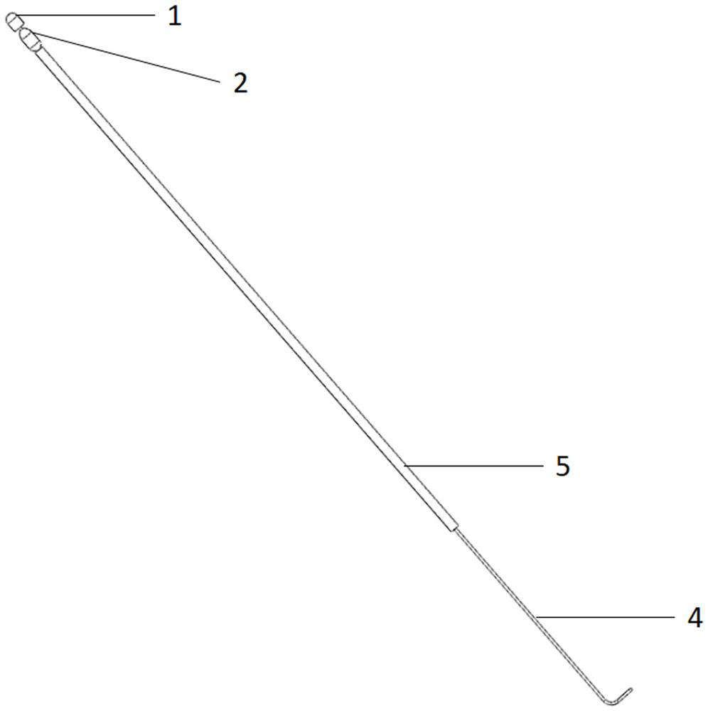
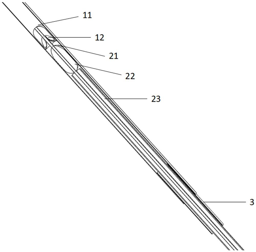
[0036] A venous valve resection device, which includes a vascular support tube 3; a resection structure 1 and a docking structure 2; the vascular support structure is a structure arranged at the initial end of a blood vessel; the front end of the resection structure 1 is a ball top structure-11, and the rear end includes a ball top Concavity, the end of the spherical top depression 12 forms a circular cutter 13; the front end of the docking structure 2 includes a spherical top protruding structure 1 21 that matches the spherical top depression 12; the rear end of the docking structure 2 is provided with a spherical top protruding structure 2 22 to ensure smooth exit; In addition, in the middle of the cutting structure 1 and the docking structure 2, the setting channel 41 of the pulling guide wire is set, wherein the setting channel 41 of the cutting structure 1 is bonded to the pulling guide wire, and the pulling guide wire does not pass through the setting channel 41 on the cut...
Embodiment 2
[0042] On the basis of Embodiment 1, add a guiding and entering structure 31 that guides the vascular support tube 3 to enter; as Figure 7 As shown, the specific setting is as follows: a guiding and entering structure 31 with a spherical top structure 311 and close to the vascular supporting tube 3 is arranged in the vascular supporting tube 3; the length of the guiding and entering structure 31 is longer than that of the vascular supporting structure, and the guiding and entering structure 31 can be Withdraw from the vascular support tube 3; when in use, combine the two, and send the vascular support tube 3 into the initial section of the blood vessel under the guidance of the guide entry structure 31, and then withdraw the guide entry structure 31; this setting is convenient and fast to insert the vascular support tube 3 Inserted into the blood vessel to facilitate subsequent operations.
Embodiment 3
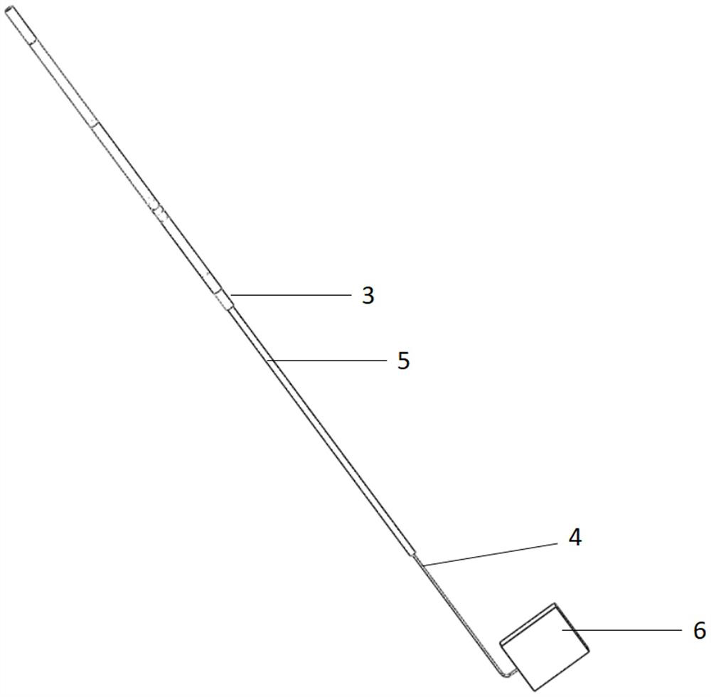
[0044] On the basis of Example 2, the heparin injection channel 32 that reduces the entry resistance of the vascular support tube 3; Figure 7 As shown, the specific configuration is as follows: a heparin injection channel 32 penetrating through the guiding structure 31 is provided in the guiding structure 31 , and heparin is injected through the heparin injection channel 32 to lubricate the guiding structure 31 . The rear end of the heparin injection channel 32 is connected to an extension tube, and the extension tube is provided with a syringe or a connector 33 of the syringe pump 6, or the rear end of the guiding structure 31 is provided with a syringe connected to the heparin injection channel 32 or a connector 33 of the syringe pump 6; Connect with the syringe or syringe pump 6 with heparin, guide the heparin into the front end of the dome structure 2 311 of the structure 31 and flow and infiltrate the entire guiding structure 31 and the vascular support tube 3 .
PUM
 Abstract
Description
Claims
Application Information