Electromagnetic thermal coupling and thermoelectric chemical oxidation equipment

An electromagnetic thermal coupling, thermoelectrochemical technology, applied in the direction of anodic oxidation, electrolytic coating, electrolytic process, etc., can solve the problems of poor fluidity of electrolyte, decrease of solution resistance, influence of ceramic layer performance, etc., to increase temperature range, cooling power The effect of reducing power consumption and reducing power consumption

Pending Publication Date: 2021-07-23
SIBERIAN MOTOR TECH SUZHOU CO LTD
View PDF0 Cites 2 Cited by
  • Summary
  • Abstract
  • Description
  • Claims
  • Application Information

AI Technical Summary

Problems solved by technology

[0003] In the prior art, the solution resistance in the electrolyte is relatively large, and the fluidity of the electrolyte is poor, which has an impact on the performance of the ceramic layer of thermoelectrochemical oxidation
In order to promote the circulation and uniformity of the electrolyte, the existing technology adds ultrasonic waves outside the electrolytic cell, which reduces the resistance of the solution accordingly, promotes the circulation and uniformity of the electrolyte, promotes the initial stage of thermoelectrochemical oxidation, and improves the surface of the workpiece. The performance of the ceramic layer, but the cost of ultrasonic is high, it is difficult to get practical application
Moreover, the power consumption of the prior art and the cooling power consumption of the electrolyte are large, resulting in high cost of workpieces for thermal electrochemical oxidation, which hinders the development and application of this field

Method used


Image

  • Electromagnetic thermal coupling and thermoelectric chemical oxidation equipment

Examples


Embodiment 1

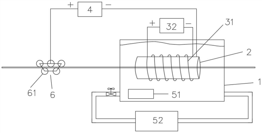
[0036] A device for thermoelectrochemical oxidation coupled with electromagnetic heat, such as figure 1 As shown, it includes: electrolytic cell 1, electrolytic cell 2, electromagnetic thermal coupling part 3, thermoelectrochemical oxidation power supply 4 and temperature control system 5, the electrolytic cell 2 is inside the electrolytic cell 1, and the electrolytic cell 2 is a hollow cylinder , the electrolytic cell 1 is used to contain the electrolyte, the electrolyte overflows the electrolytic cell 2, the electromagnetic thermal coupling part 3 is connected with the electrolytic cell 2, and the electromagnetic thermal coupling part 3 is used to control the directional movement of the charged particles in the electrolytic cell 2 through a magnetic field, The electromagnetic thermal coupling part 3 is composed of a helical coil 31 and a current source 32. The helical coil 31 is formed by helically winding an insulated wire on the outer wall of the electrolytic cell 2. The tw...


PUM


Abstract

The invention provides electromagnetic thermal coupling and thermoelectric chemical oxidation equipment. The equipment comprises an electrolytic tank, an electrolytic bath, an electromagnetic thermal coupling part, a thermoelectric chemical oxidation power supply and a temperature control system. The electrolytic bath is in the electrolytic tank and is a hollow cylinder, an electrolyte in the electrolytic tank overflows the electrolytic bath, the electromagnetic thermal coupling part is connected with the electrolytic bath, and the electromagnetic thermal coupling part is used for controlling directional movement of charged particles in the electrolytic bath through a magnetic field. The electromagnetic thermal coupling part is composed of a spiral coil and a current source, the spiral coil is formed by spirally winding an insulated wire on the outer wall of the electrolytic bath, and the two ends of the spiral coil are connected with the current source. The positive pole of the thermoelectric chemical oxidation power supply is connected with a workpiece, the negative pole of the thermoelectric chemical oxidation power supply is connected with the electrolytic bath, the workpiece is valve metal or conductive metal with the outer surface being valve metal, the workpiece is subjected to thermoelectric chemical oxidation in the electrolytic bath, and an oxidation ceramic layer grows on the surface of the workpiece in situ. The temperature control system is connected with the electrolytic tank and is used for controlling the temperature of the electrolyte in the electrolytic tank.

Description

technical field [0001] The invention relates to the technical field of thermoelectrochemical oxidation, and in particular, the invention relates to a thermoelectrochemical oxidation device coupled with electromagnetic heat. Background technique [0002] Thermoelectrochemical oxidation is a new surface treatment technology that has developed rapidly at home and abroad in recent years. It is developed on the basis of anodic oxidation, also known as micro plasma oxidation, plasma thermoelectrochemical oxidation, plasma enhanced electrochemical oxidation. Surface ceramicization, etc. Thermoelectrochemical oxidation uses a higher working voltage, the valve metal workpiece is used as the anode, and the electrolytic cell is used as the cathode. The voltage is applied to the cathode and anode through a special power supply, and the working area of ​​the voltage is introduced from the Faraday area of ​​the ordinary anodic oxidation method to the high voltage. In the discharge area, ...

Claims


Application Information

Patent Timeline
Patent Type & Authority Applications(China)
IPC IPC(8): C25D11/02C25D17/00C25D21/02
CPCC25D11/005C25D11/026C25D21/02
Inventor 李昊旻雷厉王连可
Owner SIBERIAN MOTOR TECH SUZHOU CO LTD
Why Eureka
Try Eureka