Digital phase-locking method

A digital phase-locking and phase-locking signal technology, applied in the fields of communication and control, can solve the problems of slowing down the change adjustment speed, reducing the stability of the phase-locking, and difficulty in the calculation and analysis of the phase-locking system, and achieves a simplified design process, clear steps, Good tracking speed and stability

Inactive Publication Date: 2003-12-17
TSINGHUA UNIV
View PDF0 Cites 0 Cited by
  • Summary
  • Abstract
  • Description
  • Claims
  • Application Information

AI Technical Summary

Problems solved by technology

First of all, the working principle of the pulse sequence low-pass filter counting method in the low-pass filter part is a nonlinear process, and a reasonable linear approximation cannot be made, so the transfer function of this part cannot be obtained, so it is impossible to derive the entire phase-locked system transfer function
The difficulty in calculation and analysis of existing phase-locked systems has brought inconvenience to the design and determination of parameters and the analysis of system performance
Although the aforementioned pulse sequence low-pass filter counting method only includes two design parameters of the frequency division multiple G and the frequency division multiple L, but because their values ​​cannot be obtained through quantitative analysis, they can only be tried in a specific circuit by experimental methods. Yes, this increases the difficulty of design and the workload of debugging
[0004] In terms of qualitative analysis, the two parameters G and L in the aforementioned pulse sequence low-pass filter counting method have a great influence on the phase-locking frequency range, phase-locking tracking speed and phase-locking stability of the phase-locking system
If the G and L parameters are selected to be small, the change and adjustment speed of the control parameter N will be fast, so the phase lock tracking speed is also fast, and the corresponding phase lock frequency range can be relatively large, but too small G and L parameters will reduce the lock frequency. phase stability; if the G and L parameters are selected to be large, although the phase-locking stability is improved, the adjustment speed of the control parameter N will slow down. At this time, the tracking speed of the phase-locking system is slow and the frequency of phase-locking The range will also be reduced
It can be seen that the existing phase-locked control methods are mutually restricted in terms of frequency range, speed and stability, so it is difficult to meet the overall performance requirements of the phase-locked system that can take into account all aspects.
[0005] The existing pulse sequence low-pass filter counting method only uses the pulse state of the phase error signal generated by the digital phase detection part to reflect the characteristics of the frequency difference between the locked signal and the phase-locked signal, but in fact the pulse width of the phase error signal is still It can directly reflect the instantaneous phase difference between the locked signal and the phase-locked signal, but the existing methods do not make full use of the nature of this pulse width. This principle defect will inevitably affect the final signal phase-locked performance

Method used


Image

  • Digital phase-locking method
  • Digital phase-locking method
  • Digital phase-locking method

Examples


Embodiment Construction

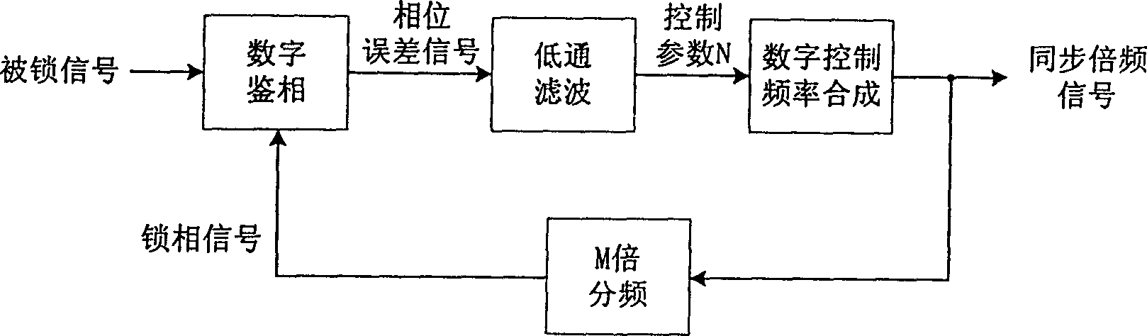
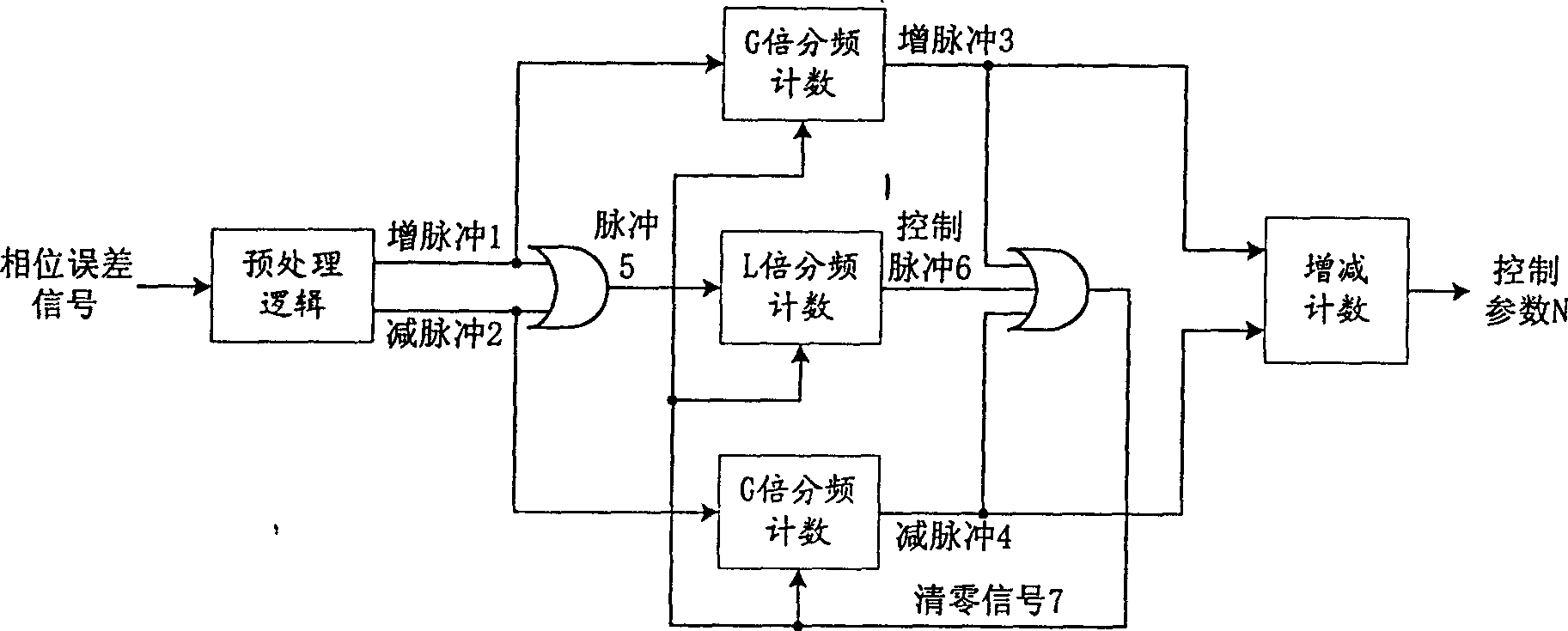
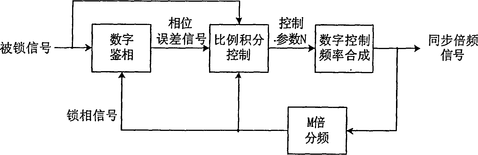
[0024] The principle block diagram of the digital phase-locking method of the present invention is as image 3 as shown, Figure 4 The block diagram shown further shows the principle structure of the proportional-integral control part in the digital phase-locking method of the present invention. refer to image 3 and Figure 4 , the working process of the digital phase-locking method of the present invention is as follows:

[0025] 1. the locked signal of input phase-locked system of the present invention is a digital square wave pulse signal, and its frequency F sig satisfy F sig ≤F sig ≤F sig ,here F sig is the lower limit of the locked signal frequency range, F sig It is the upper limit of the locked signal frequency range. The synchronous frequency-multiplied signal output by the phase-locked system of the present invention undergoes M-fold frequency division to obtain a phase-locked signal, and the phase-locked signal is fed back to the input side. The digita...


PUM


Abstract

The digital phase-locking method incldues the following steps: firstly, making digital phase discrimination of inputted locked signal to obtain phase error signal, making high-frequency modulatino pretreatment of said signal to obtain phase error signal, making high-frequency modulation pretreatment of said signal to obtain forward-backward pulse signal, then making the control pulse being in the formed-backward pulse signal undergo the process of proportional pulse frequency division to obtain proportional forward-backward pulse signal, making proportional forward-backward counting operation to obtain parameter NF', latching parameter NP' before it is cleared, outputting to obtain proportional control parameter NP, at the same time making the control pulse being in forward-backward pulse signal undergo the process is integral pulse frequency division to obtain integral forward-backward pulse signal, mkaing integral forward-backward counting operation to optain integral control parameter NI, adding parameter NP and NI, and utilizing amplitude control to obtain parameter N, under the control of it, making digital control frequency synthesis of clock signal to obtain synchronous double-frequency signal.

Description

Technical field: [0001] The invention relates to a digital phase-locking method, which can phase-lock and track an input digital pulse signal to generate a synchronous frequency multiplication signal, and can use phase-locking control parameters to detect the frequency of the input signal, and belongs to the technical fields of communication and control. . Background technique: [0002] In the fields of communication, home appliances, instrumentation, automatic control, etc., various processing or control processes often need to be carried out synchronously with an input signal, which requires the use of signal phase-locking technology. In particular, the development of the digitization direction in the above-mentioned fields needs to adopt a digital method to perform synchronous frequency multiplication and frequency detection on the locked signal. Referring to the book "Phase Locked Loop: Principles, Design and Application" with the international standard number 007005050...

Claims


Application Information

Patent Timeline
Patent Type & Authority Patents(China)
IPC IPC(8): H04L7/02
Inventor 庞浩王赞基陈建业
Owner TSINGHUA UNIV
Why Eureka
Try Eureka