Additive manufacturing method for magnesium alloy directional solidification crystal or single crystal

A technology of directional solidification and additive manufacturing, applied in the field of additive manufacturing, which can solve problems such as poor plastic deformation ability, mold shell pollution, and difficulty in preparing magnesium alloys

Pending Publication Date: 2021-07-30
UNIV OF SHANGHAI FOR SCI & TECH
View PDF11 Cites 0 Cited by
  • Summary
  • Abstract
  • Description
  • Claims
  • Application Information

AI Technical Summary

Problems solved by technology

However, since most magnesium alloys belong to the hexagonal close-packed (HCP) structure at room temperature, the plastic deformation at room temperature is limited to {0002} basal slip and {10-12} twinning, resulting in Its plastic deformation ability is poor, and the study of deformation behavior using directionally solidified grains or single crystals of magnesium alloys is of great value in revealing its deformation mechanism and improving its processing performance.
[0003] At present, most of the preparation methods for directionally solidified crystals or single crystals of magnesium alloys are cast, which has a long cycle, the need to make mold shells, and the problems of mold shell pollution.
However, as a rapid manufacturing technology, additive manufacturing technology is rarely mentioned in the field of preparing directionally solidified crystals or single crystals of magnesium alloys.
Research on the additive manufacturing of magnesium alloys is mainly aimed at selective laser melting (SLM) technology, and magnesium alloys have high reflectivity to laser light, which leads to low energy efficiency of additive manufacturing methods using lasers as heat sources, and because magnesium alloy powder The disadvantages of high preparation cost, flammability and explosion, etc., make it difficult to prepare magnesium alloys by SLM technology

Method used


Image

  • Additive manufacturing method for magnesium alloy directional solidification crystal or single crystal
  • Additive manufacturing method for magnesium alloy directional solidification crystal or single crystal
  • Additive manufacturing method for magnesium alloy directional solidification crystal or single crystal

Examples


Embodiment Construction

[0027] In order to facilitate the understanding of the present invention, the present invention will be described more fully below with reference to the associated drawings. Preferred embodiments of the invention are shown in the accompanying drawings. However, the present invention can be embodied in many different forms and is not limited to the embodiments described herein. On the contrary, these embodiments are provided to make the understanding of the disclosure of the present invention more thorough and comprehensive.

[0028] It should be noted that when an element is referred to as being “fixed” to another element, it can be directly on the other element or there can also be an intervening element. When an element is referred to as being "connected to" another element, it can be directly connected to the other element or intervening elements may also be present. The terms "vertical," "horizontal," "left," "right," and similar expressions are used herein for purposes ...


PUM


Abstract

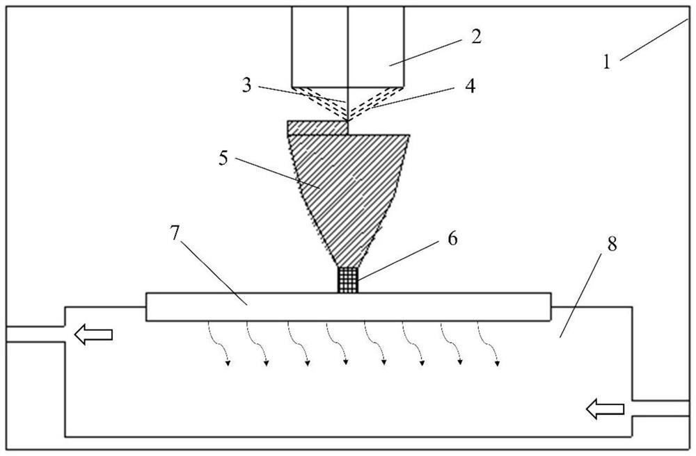
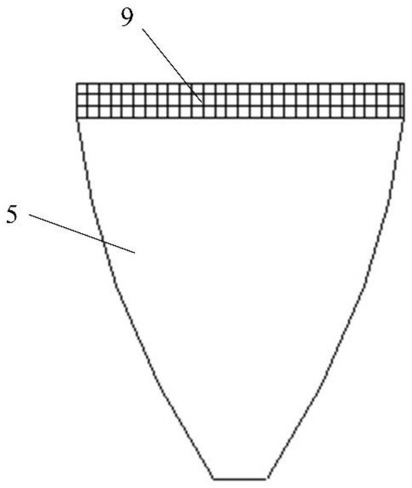
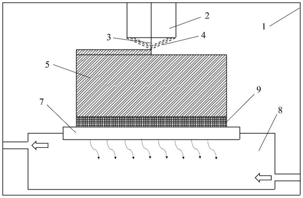
The invention discloses an additive manufacturing method for a magnesium alloy directional solidification crystal or single crystal. The method adopts an electron beam fuse wire additive manufacturing technology, and comprises a metal substrate arranged in a vacuum working cavity of electron beam fuse wire additive manufacturing equipment, a magnesium alloy single crystal seed crystal is fixed on the metal substrate, and the magnesium alloy single crystal seed crystal and a molten magnesium alloy wire are combined to form the magnesium alloy directional solidification crystal or single crystal. The manufacturing period of the magnesium alloy directional solidification crystal or single crystal can be greatly shortened, the production cost is reduced, and the material utilization rate is increased; and meanwhile, the problem that a magnesium alloy is flammable and explosive is effectively solved.

Description

technical field [0001] The invention relates to the technical field of additive manufacturing, in particular to an additive manufacturing method for directionally solidified crystals or single crystals of magnesium alloys. Background technique [0002] Due to its low density, high specific strength, and biodegradability, magnesium alloys have gradually developed into contemporary important lightweight structural materials, and have important application values ​​in the fields of automobiles, aerospace, and biomedicine. However, since most magnesium alloys belong to the hexagonal close-packed (HCP) structure at room temperature, the plastic deformation at room temperature is limited to {0002}<11-20> basal slip and {10-12}<10-11> twinning, resulting in Its plastic deformation ability is poor, and the study of deformation behavior using directionally solidified grains or single crystals of magnesium alloys is of great value for revealing its deformation mechanism an...

Claims


Application Information

Patent Timeline
IPC IPC(8): B22F10/25B22F10/32C30B29/52C30B11/00B33Y10/00
CPCC30B29/52C30B11/003C30B11/001B33Y10/00
Inventor 杨义胡嘉南吴松全林坤侯娟王皞张恺黄海军
Owner UNIV OF SHANGHAI FOR SCI & TECH
Why Eureka
Try Eureka