
In-hole delayed segmented detonating slotting structure and a slotting method

A charge hole and center hole technology, which is applied in the field of tunnel excavation, can solve problems such as easy accumulation of rock blocks, inability to achieve cutting effect, charge amount and blasting interval cannot be determined, etc.

Inactive Publication Date: 2021-07-30
NUCLEAR IND NANJING CONSTR GRP CO LTD +1
View PDF1 Cites 2 Cited by
  • Summary
  • Abstract
  • Description
  • Claims
  • Application Information

AI Technical Summary

Problems solved by technology

[0003] In the cutting of the prior art, the differential initiation technology is generally used between different holes to form a new free surface around adjacent holes, such as the technical solution proposed in Patent Document 1, although it also discloses cutting Sequential differential detonation is used in the hole to overcome the rock clamping effect and increase the depth of the cycle footage; however, the time interval in the prior art is fixed, which is only suitable for the coal mines in the Hengyan area of ​​northern Anhui, and it is used when the rock hardness is different. , due to the different tearing and disintegration times of rocks by blasting, the amount of charge and the interval between blasting cannot be determined, and a good cutting effect cannot be achieved. In addition, the technical solution is easy to accumulate rock blocks during cutting, which is not conducive to the overall Subsequent expansion of the working area to the airport

Method used


Image

  • In-hole delayed segmented detonating slotting structure and a slotting method
  • In-hole delayed segmented detonating slotting structure and a slotting method
  • In-hole delayed segmented detonating slotting structure and a slotting method

Examples


Embodiment Construction

[0040] In order to better understand the technical content of the present invention, specific embodiments are given together with the attached drawings for description as follows.

[0041] Aspects of the invention are described in this disclosure with reference to the accompanying drawings, which show a number of illustrated embodiments. Embodiments of the present disclosure are not necessarily intended to include all aspects of the invention. It should be understood that the various concepts and embodiments described above, as well as those described in more detail below, can be implemented in any of a number of ways in any of the in-hole delayed staged initiation cut structures and methods, because the present invention The concepts and embodiments disclosed are not limited to any implementation. In addition, some aspects of the present disclosure may be used alone or in any suitable combination with other aspects of the present disclosure.

[0042]When the explosive in th...


PUM

PropertyMeasurementUnit
Diameteraaaaaaaaaa
Diameteraaaaaaaaaa

Abstract

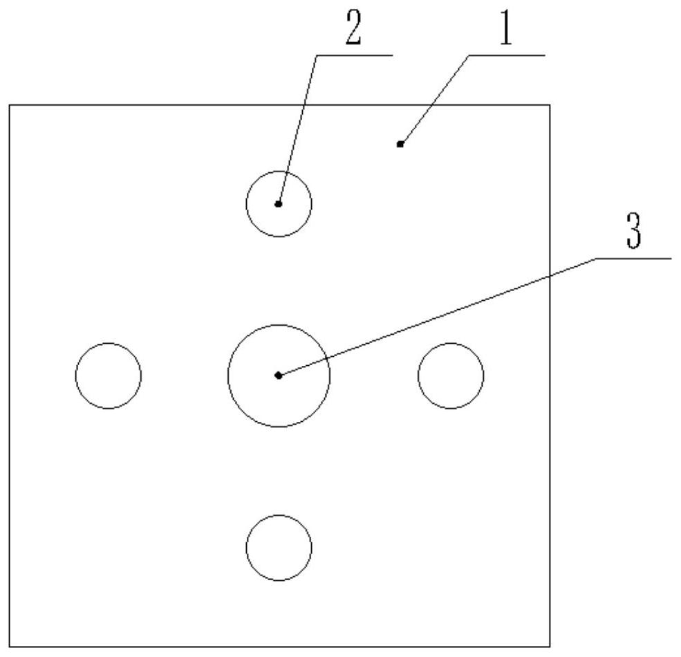
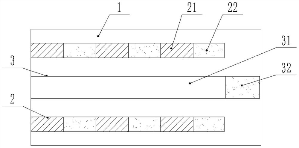
The invention relates to the technical field of tunneling, in particular to an in-hole delayed segmented detonating slotting structure and a slotting method. The structure comprises a center hole which is formed in a tunneling working face, and charging holes formed in the tunneling working face and distributed at the periphery of the center hole, wherein a blocking section and a charging section are arranged in each charging hole at intervals, the charging sections are arranged to be detonated at intervals from outside to inside, and the throwing charging sections are arranged at the bottoms of the blocking sections and used for exploding and throwing broken stones after explosives in the charging holes explode; through interval segmented detonation in the holes, when stress waves spread from front-end charging to rear-end charging do not completely disappear, rear-end charging is detonated, so that a rock mass to be exploded receives bidirectional stress, the crushing effect is improved, and the interaction among broken stones is also increased; and when delayed blasting is adopted, vibration waves generated by blasting can be weakened due to mutual interference, so that the vibration effect on the surrounding environment is reduced, and safe development of blasting operation is facilitated.

Description

technical field [0001] The invention relates to the technical field of tunnel excavation, in particular to a structure and method for delayed and segmented detonation cut in a hole. Background technique [0002] Cutting blasting is the first process of tunneling engineering. Its main function is to blast out new free surfaces and create favorable blasting conditions for other blast holes. Its blasting effect affects the blasting effect of the entire section and the utilization rate of blast holes. The groove quality determines the depth of footage in a single cycle. [0003] In the cutting of the prior art, the differential initiation technology is generally used between different holes to form a new free surface around adjacent holes, such as the technical solution proposed in Patent Document 1, although it also discloses cutting Sequential differential detonation is used in the hole to overcome the rock clamping effect and increase the depth of the cycle footage; however,...

Claims


Application Information

Patent Timeline
IPC IPC(8): F42D1/00F42D1/08F42D3/04
CPCF42D1/00F42D1/08F42D3/04
Inventor 王凯顾云薛君卫孙飞刘勤杰倪国庆杨炎李克坤刘迪
Owner NUCLEAR IND NANJING CONSTR GRP CO LTD
Learn More