Non-contact flexible transparent sensor and preparation method thereof

A non-contact, sensor technology, applied in the field of flexible sensors, can solve the problems of difficult monitoring, weak output induction signal, and difficult integration of external equipment

Pending Publication Date: 2021-08-06
XI AN JIAOTONG UNIV
View PDF4 Cites 1 Cited by
  • Summary
  • Abstract
  • Description
  • Claims
  • Application Information

AI Technical Summary

Problems solved by technology

[0003] At present, there are two main problems in the non-contact sensing method that uses the static electricity of the human body as the natural signal source: one is that the output induction signal is usually weak due t

Method used


Image

  • Non-contact flexible transparent sensor and preparation method thereof
  • Non-contact flexible transparent sensor and preparation method thereof
  • Non-contact flexible transparent sensor and preparation method thereof

Examples


Embodiment 1

[0049] 1) Place the PET substrate in an inductively coupled plasma etching chamber, introduce oxygen into the vacuumed chamber, and then apply a power of 150W to etch for 150s to realize the preliminary nanostructure design of the substrate;

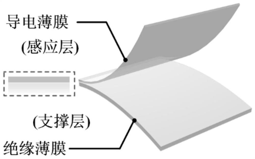
[0050] 2) Transfer the rough surface to the coating equipment. After vacuuming the cavity, deposit the conductive transparent material ITO on the surface of the sample to form an induction layer. The type and thickness of the deposited film can be controlled by controlling the type of target and the deposition time;

[0051] 3) Prepare signal output electrodes at the four ends of the sensor for outputting horizontal and vertical signals;

[0052] 4) By collecting and analyzing the four-terminal output signals, the corresponding operation commands are realized.

Embodiment 2

[0054] 1) Place the PDMS substrate in an inductively coupled plasma etching chamber, introduce oxygen into the vacuumed chamber, and then apply a power of 100W to etch for 200s to realize the preliminary nanostructure design of the substrate;

[0055] 2) Transfer the rough surface to the coating equipment. After vacuuming the cavity, deposit the conductive transparent material ITO on the surface of the sample to form an induction layer. The type and thickness of the deposited film can be controlled by controlling the type of target and the deposition time;

[0056] 3) Prepare signal output electrodes at the four ends of the sensor for outputting horizontal and vertical signals;

[0057] 4) By collecting and analyzing the four-terminal output signals, the corresponding operation commands are realized.

Embodiment 3

[0059] 1) The glass substrate is placed in the reactive ion etching chamber, and the SF 6 Pass it into the vacuumed cavity, and then apply a power of 120W to etch for 150s to realize the preliminary structural design of the substrate;

[0060] 2) Transfer the rough surface to the coating equipment. After vacuuming the cavity, deposit the conductive transparent material ITO on the surface of the sample to form an induction layer. The type and thickness of the deposited film can be controlled by controlling the type of target and the deposition time;

[0061] 3) Prepare signal output electrodes at the four ends of the sensor for outputting horizontal and vertical signals;

[0062] 4) By collecting and analyzing the four-terminal output signals, the corresponding operation commands are realized.


PUM

PropertyMeasurementUnit
Thicknessaaaaaaaaaa
Thicknessaaaaaaaaaa

Abstract

The invention discloses a non-contact flexible transparent sensor and a preparation method thereof, and belongs to the field of flexible sensors. The conductive induction layer is deposited on the surface of the insulation supporting layer, and the contact surface of the insulation supporting layer and the conductive induction layer is a composite rough surface; redistribution of charges on the surface of the sensing layer caused by hand movement is detected by adopting four ends, so that non-contact sensing and control based on gestures are realized. The double-layer structure has universality, the sensing layer can be made of conductive films such as indium tin oxide, copper and the like, and the supporting layer can be made of glass, quartz, a display screen and the like. On the other hand, a rough structure is prepared on the surface of the sensing layer through a plasma etching process, so that the specific surface area is increased, the output signal of the sensor is greatly improved, and higher sensitivity is provided for the near-field sensor.

Description

technical field [0001] The invention belongs to the field of flexible sensors, and relates to a non-contact flexible transparent sensor and a preparation method thereof. Background technique [0002] Non-contact sensing methods have received extensive attention due to their great potential in human-computer interaction, health monitoring, and hospital healthcare. Compared with contact sensing, non-contact sensing is more convenient in some occasions, such as wireless The interaction of physical contact may help to reduce the chance of spreading pathogens such as the COVID-19 virus, thus controlling electronic devices through contactless methods is a promising research area. [0003] At present, there are two main problems in the non-contact sensing method that uses human body static electricity as the natural signal source: one is that the output induction signal is usually weak due to the limited charge carried by the human body, and it is difficult to monitor. Another is ...

Claims


Application Information

Patent Timeline
IPC IPC(8): G06F3/041G06F3/01
CPCG06F3/041G06F3/017G06F2203/04102G06F2203/04108
Inventor 杨雷陈思成郭艳婕汪云飞王淼
Owner XI AN JIAOTONG UNIV
Why Eureka
Try Eureka