Machining equipment integrated with force sensor and ultra-precision cutting tool setting method

A technology of processing equipment and sensors, applied in metal processing equipment, metal processing, metal processing mechanical parts, etc., can solve the problems of affecting the accuracy of tool path planning, limited tool setting accuracy, and complicated operation, so as to ensure the accuracy of tool path planning. , The effect of high degree of tool setting automation and simple tool setting process

Pending Publication Date: 2021-08-13
ZHEJIANG UNIV
View PDF0 Cites 1 Cited by
  • Summary
  • Abstract
  • Description
  • Claims
  • Application Information

AI Technical Summary

Problems solved by technology

This method has the following deficiencies: (1) This method requires high operating experience of the operator, and the operation is cumbersome; (2) The accuracy of the optical tool setting instrument is limited by the depth of field and resolution of the tool setting instrument. (3) For the ultra-precision cutting of some special components, such as the inner wall of small-sized components, it is difficult to install other instruments such as optical tool setting instruments in the cramped processing space, so it is impossible to Realize the corresponding precise tool setting operation; (4) The optical tool setting instrument can only position the tip of the tool on the surface of the workpiece, but for rotary workpieces, it cannot accurately position the tip of the tool at the center of rotation of the spindle, which affects the accuracy of subsequent tool trajectory planning

Method used


Image

  • Machining equipment integrated with force sensor and ultra-precision cutting tool setting method
  • Machining equipment integrated with force sensor and ultra-precision cutting tool setting method
  • Machining equipment integrated with force sensor and ultra-precision cutting tool setting method

Examples


Embodiment Construction

[0062] The present invention will be further described below in conjunction with specific embodiment:

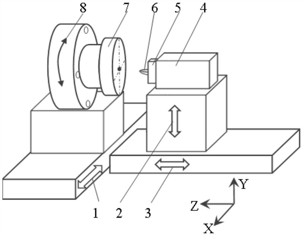
[0063] like figure 1 As shown, a processing device integrating a force sensor includes a frame, a spindle 8, a processing device 4, a tool 6, a three-axis driving device, a position transmission device, and a tool setting control system.

[0064] A main shaft 8 for driving the workpiece 7 to rotate is installed on one side of the frame, a rotary encoder for outputting the rotational position is installed in the main shaft 8 , and a clamp for clamping the workpiece 7 is arranged at the end of the main shaft 8 . A processing device 4 is installed on one side of the frame, and a cutter 6 is arranged on a side of the processing device 4 close to the clamp, and the cutter 6 is a diamond cutter 6 for ultra-precision cutting of the workpiece 7 . Wherein, the processing device 4 may be a processing device 4 commonly used in ultra-precision cutting such as fast tool servo and slow ...


PUM


Abstract

The invention belongs to the technical field of precision manufacturing equipment, and particularly relates to machining equipment integrated with a force sensor and an ultra-precision cutting tool setting method. The machining equipment comprises a main shaft, a tool, a three-axis driving device, a position transmission device and a tool setting control system. The tool setting control system comprises the force sensor and a PID controller. The force sensor is arranged on the tool and used for detecting contact force between the tool and a workpiece. The PID controller controls a Z-direction driving mechanism to work according to the magnitude of the contact force. According to the machining equipment integrated with force sensor and the ultra-precision cutting tool setting method, the contact force / cutting force closed-loop feedback control function and the scanning measurement function are achieved, the ultra-precision cutting tool setting method is researched and developed based on the above functions, ultra-precision tool setting can be achieved, other instruments are not needed, the tool setting requirement under the condition that the machining range space is limited, and other tool setting instruments are difficult to install is met, and universality is achieved. Meanwhile, the operation process of tool setting is simplified, and the automation degree of tool setting and the tool setting precision are greatly improved.

Description

technical field [0001] The invention belongs to the technical field of precision manufacturing equipment, in particular to a processing equipment integrating force sensors and an ultra-precision cutting tool setting method. Background technique [0002] Ultra-precision cutting technology is an important means for manufacturing optical components with micro-nano fine structure or high-precision morphology. It is widely used in the fields of aerospace, national defense and military industry, information communication, life science and material science. important branch in . Ultra-precision cutting based on single-point diamond, using ultra-precision lathes with nano-machine positioning accuracy and diamonds with sharp edges, high hardness, and good wear resistance as tools, the geometry is formed by precisely controlling the relative motion trajectory between the tool and the workpiece The surface has the advantage of being able to obtain nano-scale surface roughness and sub-...

Claims


Application Information

Patent Timeline
Patent Type & Authority Applications(China)
IPC IPC(8): B23D79/00B23Q1/62B23Q15/22
CPCB23D79/00B23Q1/62B23Q15/22
Inventor 陈远流陈甫文林焕彬李忠伟居冰峰
Owner ZHEJIANG UNIV
Why Eureka
Try Eureka