Supercharge Your Innovation With Domain-Expert AI Agents!

Optical lens detection system and detection method

An optical lens and detection system technology, applied in the field of spherical or aspheric mirror detection systems, can solve the problems of large influence on process accuracy, long time-consuming, time-consuming process, etc., and achieve the effects of improving detection accuracy, improving detection efficiency, and avoiding movement

Active Publication Date: 2021-08-24
CHANGCHUN INST OF OPTICS FINE MECHANICS & PHYSICS CHINESE ACAD OF SCI
View PDF10 Cites 1 Cited by
  • Summary
  • Abstract
  • Description
  • Claims
  • Application Information

AI Technical Summary

Problems solved by technology

The three-coordinate detection has certain restrictions on the caliber of the lens, and it takes a long time. The CGH method is greatly affected by the process accuracy. The Hardman and interferometer detection accuracy is high, but the measurement range is small. In the rough processing stage, the surface shape is rough. Large degree, hardman and interferometer detection is more difficult
The Ronchi grating detection method can realize the detection from fine grinding to initial polishing by adjusting the frequency of the grating, which is suitable for the guidance detection of the rough machining process, but it is difficult to quantitatively test the surface parameters in the later stage of fine polishing, requiring an interferometer take measurements
Rough machining and fine machining require two sets of testing equipment. To replace the testing equipment, sometimes it is necessary to move the inspected mirror to a specific inspection area, which is time-consuming, laborious and risky
Replacing the detection equipment requires realigning the optical axis, which is a time-consuming process

Method used


Image

  • Optical lens detection system and detection method
  • Optical lens detection system and detection method
  • Optical lens detection system and detection method

Examples


Embodiment Construction

[0035] In order to make the object, technical solution and advantages of the present invention clearer, the present invention will be further described in detail below in conjunction with the accompanying drawings and specific embodiments. It should be understood that the specific embodiments described here are only used to explain the present invention, but not to limit the present invention.

[0036] The object of the present invention is to provide an optical lens inspection system and inspection method, the system and method can simultaneously complete the inspection of large-diameter spherical mirrors or aspheric mirrors from rough machining to fine polishing.

[0037] The optical lens inspection system and inspection method provided by the present invention will be described in detail below through specific embodiments.

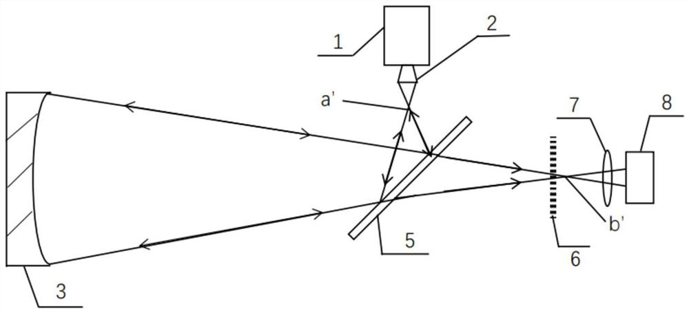
[0038] In one embodiment of the invention, see figure 1 The schematic diagram of the detection optical path when the mirror to be inspected is a spher...


PUM


Abstract

The invention belongs to the technical field of optical detection, and provides an optical lens detection system and method. A spherical wave emitted by an interferometer is focused on a first focus through an interferometer lens, a spectroscope is arranged on a light emitting path of the interferometer and is used for reflecting a beam of light reflected by a to-be-detected lens into the interferometer according to an original light emitting path. The formed interference fringes are used for guiding finish machining of the to-be-detected mirror; the other light beam is converged at a second focus after penetrating through the spectroscope; the Ronchi grating is arranged in a transmission light path of the spectroscope and does not coincide with the position of the second focal point; and the light beam modulated by the Ronchi grating enters the imaging lens group to form Ronchi grating stripes for detecting rough machining defects of the surface type of the to-be-detected lens. The Ronchi grating and the interferometer can be adopted in the same light path for detection at the same time, rough machining in the machining process can be detected, the fine polishing process can also be detected, and the detection results of the Ronchi grating and the interferometer can be compared and corrected in real time.

Description

technical field [0001] The invention belongs to the technical field of optical detection, and in particular relates to a spherical or aspheric mirror detection system and detection method combined with a Ronchi grating and an interferometer. Background technique [0002] Large-diameter aspheric mirrors are widely used in aerospace, astronomical observation, shooting range measurement and other fields. At present, the diameter of large-diameter aspheric mirrors is getting larger and larger, and the requirements for processing and testing of large-diameter aspheric mirrors are also getting higher and higher. The processing of aspheric mirrors includes steps such as rough processing and fine polishing, and the inspection of the processing process also needs to be followed up in real time. [0003] At present, the main detection methods for large-aperture aspheric mirrors include the three-coordinate method, the Hardman method, the CGH method, and the interferometer method. The...

Claims


Application Information

Patent Timeline
IPC IPC(8): G01M11/02
CPCG01M11/02G01M11/0207
Inventor 包兴臻赵楠何锋赟
Owner CHANGCHUN INST OF OPTICS FINE MECHANICS & PHYSICS CHINESE ACAD OF SCI
Features
  • R&D
  • Intellectual Property
  • Life Sciences
  • Materials
  • Tech Scout
  • Unparalleled Data Quality
  • Higher Quality Content
  • 60% Fewer Hallucinations
Learn More