Stamping system for vehicle silencing element

A technology for muffler components and vehicles, applied in the field of machining, can solve problems such as cumbersome steps, and achieve the effect of improving the degree of automation

Active Publication Date: 2021-08-31
CHONGQING ZHIMAO MACHINERY MFG
View PDF5 Cites 0 Cited by
  • Summary
  • Abstract
  • Description
  • Claims
  • Application Information

AI Technical Summary

Problems solved by technology

However, the oiling operation in the prior art mostly adopts manual oiling operation, and after the oiling is completed, the workpiece is transferred to the hydraulic press for stamping, and the steps are cumbersome

Method used


Image

  • Stamping system for vehicle silencing element
  • Stamping system for vehicle silencing element
  • Stamping system for vehicle silencing element

Examples


specific Embodiment approach

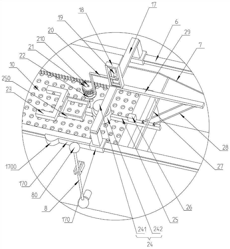
[0045] First place the workpiece to be punched under the vacuum chuck 22, the vacuum chuck 22 will absorb the upper surface of the workpiece, and then push the portal frame 17 to walk on the first slideway 6, while the portal frame 17 is walking, it also drives oiling frame walking, the driving rod 27 on the oiling frame walks along the first horizontal section 71, the first transition section 72, the second horizontal section 73, the second transition section 74 and the third horizontal section 75 successively, when the driving rod 27 is positioned at the first When in the first horizontal section 71, the vacuum chuck 22 is separated from the support core 241, which is convenient for the workpiece to be placed on the vacuum chuck 22. When the driving rod 27 is located in the second horizontal section 73, the vacuum chuck 22 and the support core 241 are close to each other, and the two The one is in the concentric position vertically, and the two clamp the workpiece.

[0046] ...


PUM


Abstract

The invention discloses a stamping system for a vehicle silencing element. The invention relates to the field of machining, and particularly discloses a stamping system which comprises a stamping machine body, a workbench, a lower die and an upper die, wherein the workbench is further provided with an oil coating mechanism, and the oil coating mechanism comprises a conveying oil-coating frame and an oil coating groove; the middle section of the oil coating groove is an oil storage section in which hydraulic oil is stored, an oil coating assembly used for spraying the hydraulic oil upwards is arranged in the oil storage section, and a first slide way and a second slide way are formed in the positions, above the oil coating assembly, of the two side walls of the oil coating groove; the conveying oil-coating frame comprises a conveying frame and an oil-coating frame, the conveying frame is slidably connected into the first slide way, and the oil-coating is slidably connected into the second slide way. By the adoption of the stamping system, automatic oil-coating before workpiece stamping can be achieved, and the automation degree of workpiece stamping is improved.

Description

technical field [0001] The invention belongs to the technical field of mechanical processing, and in particular relates to a stamping system for a sound-absorbing element for a vehicle. Background technique [0002] The automobile exhaust system is mainly composed of three sections: the head section, the middle section and the tail section. The most important structure mainly includes the exhaust manifold, the three-way catalytic converter, the front muffler, the rear muffler, the exhaust tailpipe and so on. Among them, the function of the exhaust manifold is to introduce the exhaust gas in the exhaust process of the engine into the exhaust system; the function of the three-way catalytic converter is to convert the three harmful gases of CO, HC and NOx in the exhaust into carbon dioxide, nitrogen, Harmless gases such as hydrogen and water; the main function of the muffler is to control the exhaust sound. [0003] Among them, the components of the muffler are usually formed ...

Claims


Application Information

Patent Timeline
Patent Type & Authority Applications(China)
IPC IPC(8): B21D22/02B21D37/10B21D37/18B21D43/04B21D43/18B21D45/02B21D53/88B05B9/04B05B13/02
CPCB21D37/10B21D22/02B21D53/88B21D45/02B21D37/18B21D43/18B21D43/04B05B9/047B05B13/0228
Inventor 易华
Owner CHONGQING ZHIMAO MACHINERY MFG
Why Eureka
Try Eureka